
One of the last significant steps in a project is designing the custom PCB. This stage means creating a DIY Arduino board that is custom to the application. Two examples of my past projects are BinBoo, a Binary Clock, and Open Vapors, my reflow oven controller.
While working on a project for a friend, I got to thinking; it would be nice to have a checklist for circuit elements to include on a DIY Arduino board. In the early days, I forgot to add a filter cap to AREF, for example.
These tips are based on an 8-bit AVR design, like the ATmega328p chip. You could apply these tips to other 8-bit AVRs. Until now, I have not designed a custom board around a 32-Bit/ARM board. Though at only $16, I would be tempted to just solder the Teensy module directly to my finished board.
Below is a written list of items for a DIY Arduino checklist. If you’d like to see me design this board in KiCad, check out this AddOhms Tutorial.
Main processor – ATmega328p
Most of my custom boards either use the ATmega328p or the ATmega32u4. When I want serial-USB communication, I go directly to the 32u4. I always design in surface mount versions of the parts. For the ATmega328p-AU, which comes in a 32-TQFP package. My surface mount reflow process handles that just fine. For the 32u4 I stick to the QFP-44.
The main checklist item here, pick the right package.
Oscillator
The clock signal makes everything happen inside of a microcontroller. The 328p does have two internal oscillators: an 8 MHz and 128 kHz. But these are RC-oscillators. When the temperature varies, so will the clock signal generated by an RC oscillator. This limitation is only a limit if you need precision timing in your DIY Arduino. If you are not going to use asynchronous serial communication, the internal oscillators might work just fine.
Crystal Oscillator Load Capacitors
Unless board space is limited or cost is a huge concern, I prefer using a crystal. Crystals require a couple of load capacitors to form the oscillator circuit. This Microchip application note is an excellent resource to understand Crystal Oscillator Basics.
Fortunately, Atmel (now Microchip) did provide some recommended values in their datasheet.
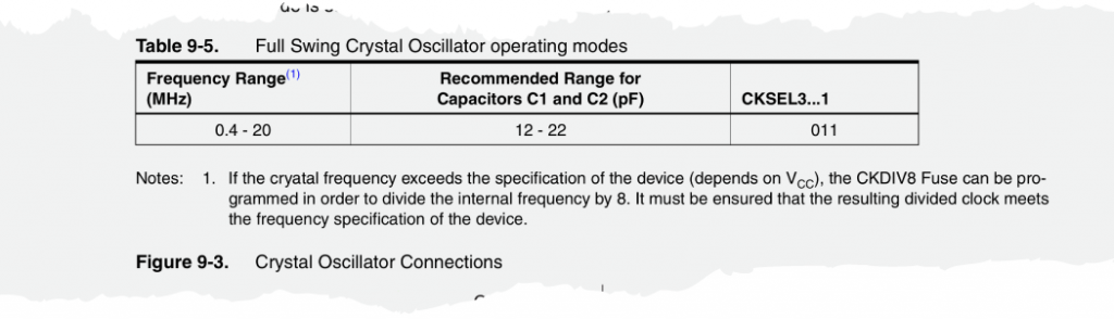
They recommend anything between 12pF and 22pF. Use the same value for both capacitors. One recommendation I have is that you use an ultra-stable ceramic capacitor. So look for something with a “C0G dielectric.” These have no, or almost no, change with applied voltage, temperature or time.
VCC Decoupling Capacitors
You need a decoupling capacitor for each VCC pin. I typically use 100 nF X7R ceramic capacitors rated for at least 16 volts. The higher rated voltage makes sure the DC-bias effect is minimized even up to 5 volts.
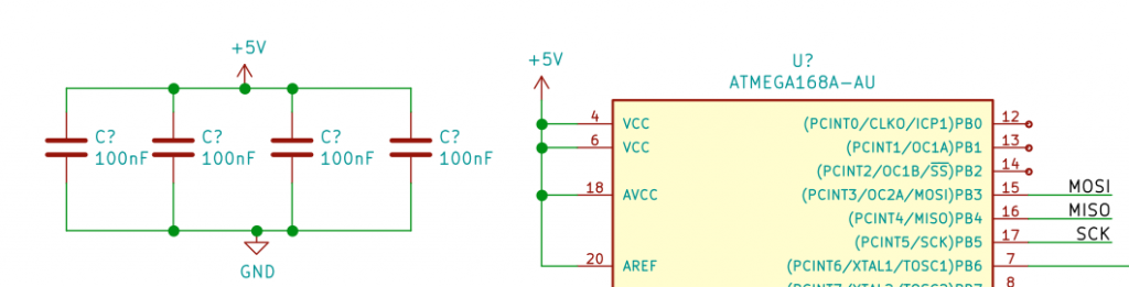
In there are more than 6 inches between my regulator and my microcontroller, I also add a 1 uF ceramic capacitor near the IC. Again, I stick to X7R and just get the highest rated voltage I can find.
RESET Pushbutton
Generally, on my schematics, I keep signals like RESET as “node labels” instead of wires running all over the board. Just use the same word each place you need the RESET signal. On boards using the Arduino bootloader, I add a pull-up for the auto-reset circuit. WIthout the bootloader, I usually skip the resistor and just use the internal pull-up on the RESET pin.
AUTO RESET
If you are only directly programming your DIY Arduino’s with an external programmer, you can skip this section. To use the Arduino bootloader to program over USB, or serial, you have to add a few more parts. At some point, I will do a more in-depth write-up on how auto-reset works. For now, there are two required components: a 100 nF capacitor and a 100 K resistor.
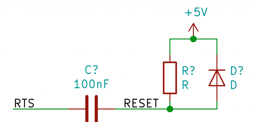
You can get away without the extra diode. However, you are running the risk of the capacitor discharging and causing a glitch above VCC. If you have room for it on the board, use it. (I have not placed it on any of my custom boards, but after some iCircuit simulations, I am starting to think I am getting lucky.)
How Arduino Auto-Reset Works (Short Version)
Whenever the serial port is inactive, the DTR signal is held high. So both sides of the capacitor are high, thanks to the pull-up resistor. When the port opens, DTR goes low, discharging the capacitor to zero volts.
This brief drop to zero resets the 328p. Eventually, the capacitor recharges through the pull-up resistor, bringing the processor out of reset and letting it boot.
Simple but very effective hack.
Power Regulators for DIY Arduino
If your board is USB powered, there is not much you need to do. Add a USB port and a ten to forty-seven microfarad capacitor. Keep in mind that USB does have an in-rush current specification. So, I would not use more than 47 µF.
Linear Regulator (LDO)
When using a linear regulator, I like the NCP1117. It is available in popular fixed voltages as well as an adjustable version. Depending on the package it can output up to one amp. The drop-out voltage is around 1 volt for 100 mA loads. It is a great little regulator for a DIY Arduino board.
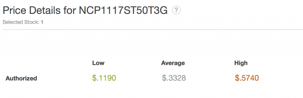
Also, it is not very expensive even in low quantities.
Power Pins
When using an onboard regulator, think about how to add power from external sources. Even if you are going to use a barrel jack or some other application-specific connector, consider header pins. These will let you bypass the barrel jack, provide extra power connections for other devices, or an accessible debug point.
I/O Pin Header
In designs where I have header pins, either generic or application specific, I always try to add extra ground pins. It seems like I am always short a couple.
Serial Header
I do not like adding an extra USB-to-serial chip. One reason is that for designs that I want USB, I use something like the 32u4. It already has a USB interface built-in. Instead, I add an FTDI-style header pin. This addition lets boards like Adafruit’s FTDI Friend easily plug in.
One benefit of this approach is that it emulates TX or RX LEDs and a bunch of other parts.
Power LEDs
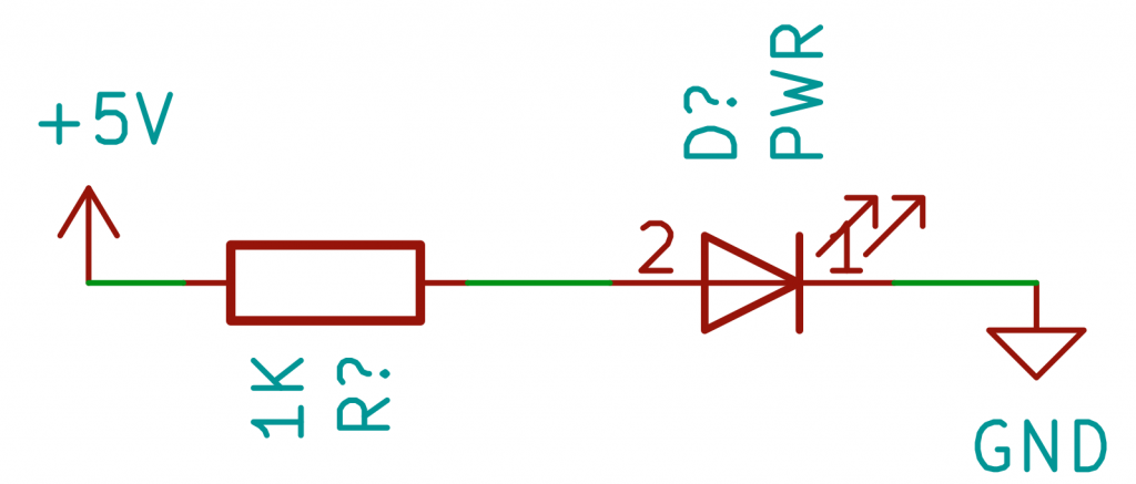
Don’t forget the most important part: a power LED. Since the LED is an indicator, use a large resistor like a 1 Kohm. You only need a few milliamps to see when the board is on. Don’t calculate a limiting resistor to drive the LED with 20mA. That is a waste of power, it will be too bright, and it will draw more current than the 328p!
Conclusion
Those are the elements I include or at least check-off when designing a DIY Arduino. In addition to the custom pieces for an application specific board, what do you add?


12 Comments
flux capacitor
One diagram shows AREF connected to +5V. I would think it better to leave it floating (with capacitor) because then you have the option of using the internal reference, which gives a measurement not dependent on the value of the supply voltage. Is there a benefit in connecting AREF to +5V?
Ah good catch. In the next revision of the schematic, I did not tie AREF to VCC. (but forgot to mention it in the PCB episode.)
I gave it a decoupling capacitor but connected it to an external pin. This is similar to how the Arduino Uno and Nano handle it.
MOSFET
Capacitor 🙂
LED
Thermistor
Diode
I am the first to admit that I understand only a small fraction of this article, but sometimes I read stuff I don’t understand until something clicks… but sometimes it never clicks and I move on. I may have missed something but I suspect the section on oscillators might need proof reading. For instance:
“An oscillator circuit generates generated from an oscillator circuit.”
and
“When the temperature values, so will the clock signal generated by an RC oscillator.”
I’m sure that if you know what this means it is easy to see what these sentences meant to say. But it was a brick wall for me. Nevertheless I will plug on and see what the next post brings.
Typos. Though the oscillator sentence bugs me. I remember deleting it. It was two statements that I started to edit and then decided they were not necessary. Thank you for the heads up.
Fixed reset button 🙂 Great tutorial!
LDR