

Here are some ideas of what you can do with the humble voltage divider. This elementary circuit has a few inventive uses. To be upfront, one of these uses is NOT as a voltage regulator. If you need a voltage regulated, get a voltage regulator! At some point or another, I’ve built all five of these voltage divider circuits. For me, the voltage level shifter is the most common.
- Measure Battery Voltage
- Signal Level Shifter
- Reference Voltage
- R-2R Ladder
- One Analog Input with Many Buttons
#1 Measure Battery Voltage
There are a couple of different cases where you might need to “step down” your battery voltage. In this case, this is NOT a substitute for a buck regulator. Instead, you might need to step down the battery voltage to measure it. Let’s say you are using a 3v3 microprocessor (Raspberry Pi) or ESP8266 (Microcontroller). Your board is being powered by two LiPos in series. Together these batteries create a supply of 7.4 volts.
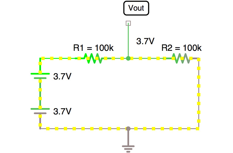
Problem using Simple Voltage Divider Circuits
Two 100kohm resistors divide the voltage from 7.4 to 3.7 volts. While easy, that is still too high for a most 3.3 volt systems. (At least the ones you want to last.) When splitting the voltage in half does not work, I turn to this voltage divider calculator. With R1 at 100kOhm and R2 at 68kOhm, the divider outputs about 3.0 volts. Simple enough, right?
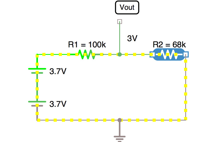
Well, there are two problems.
Leakage Current
First, connecting these two resistors in series to the battery will create a leakage current. No matter what else is going on in the circuit, 44 µA will flow through the divider. Sounds small, but that means 325 µWatts of wasted power. With USB there is little concern about that much leakage. When powered by batteries, however, that leakage means less battery life.
Back powering
If your board stays on all of the time the battery is connected, then “back feed” or “back powering” is an issue for you. Here, let’s say you take the simple divider from above and leave it connected to the analog pin. At the microcontroller, you add a switch to turn it off. Now, this switch turns off VCC but not the battery voltage.
This circuit will cause the voltage divider to “power” the microcontroller through the I/O pin. This path can damage the microprocessor and means your battery-powered circuit stays powered! So you need a way to avoid back powering your circuit.
Add transistors to voltage divider circuits
Most applications do not need continuous battery voltage monitoring. What if you could just turn on the voltage divider when you make the measurement? Ah-ha! Here’s a solution. Add a high-side PNP transistor to the simple voltage divider. A digital I/O pin controls a NPN, which turns the PNP on and off. With this configruation, no current can sneak through the analog pin’s protection diodes. And you have full control over how long the divider is activated.
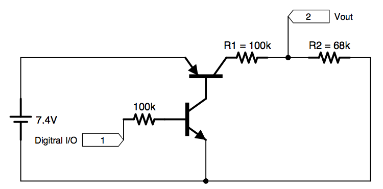
You’ll need to do some math to account for the voltage drop across the transistor, but this circuit solves the two problems: 1) leakage current is minimized and 2) no back powering through the analog pin.
Raspberry Pi Battery Measurement (without Analog)
Wait a minute; I mentioned the Pi. To read a battery voltage, don’t you need an analog-to-digital converter? Yes, you do, sometimes. An ADC is necessary to measure precise voltages. If you’re just looking for a low battery indicator, treat it as a digital signal! You could set the divider to 2.35 volts based on your battery’s “low voltage.” Any battery voltage above that point will give a larger value than 2.35 volts, which is the logic-high threshold of the Pi’s GPIO pins.
#2 Voltage Level Shifter
Modern microcontrollers are based on 3v3 logic with 1v8 logic right behind it. Using older 5.0-volt technology means you need to voltage-shift I/O signals. For example connecting an Arduino Uno’s output directly to an ESP8266 input can cause damage. (I don’t care what you read on that random forum. Don’t connect 5.0-volt logic to 3.3-volt boards!) Like I said this is the most common of the voltage divider circuits that I build.
One option is to use an application-specific chip. TI’s TXB0108 Bi-Direction shifter is one example. If you are interested in that chip, Adafruit offers a breakout board with it. This chip is designed for bi-directional operation. I2C signals are an example of a bi-directional bus. Serial, or UART, is a case of a unidirectional signal pair. So to connect serial between a 5.0-volt and 3.3-volt system, you need logic shifting.
I bet when I called this article “voltage divider circuits,” you didn’t expect two voltage divider examples in a row, right? For uni-directional signals just put two resistors in series and tap it’s Vout to go to the I/O pin. Good values to use here are R1 at 10kohm and R2 at 15kohm.
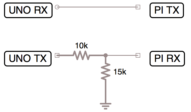
Keep in mind signals going from the 3v3 system to the 5v0 system, don’t need shifting. The Raspberry Pi’s output voltage is high enough for an Arduino Uno to see it as a logic high. It is only when you go from 5.0 to 3.3 volts you need the voltage divider.
#3 Reference
Not all voltage divider circuits use just resistors. One example contains a resistor and diode.
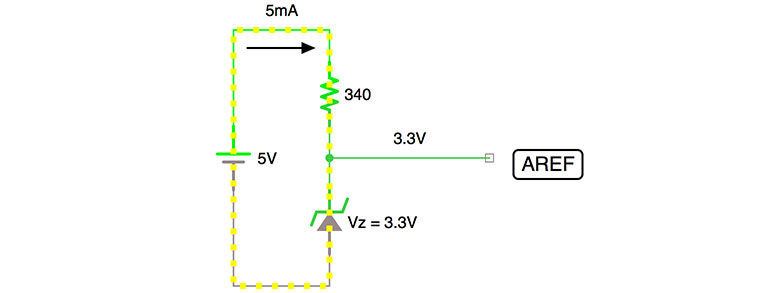
The diode’s reverse voltage creates a precision reference voltage. The resistor creates a series circuit, just like when used with an LED. Zener diodes are often used to create these reference voltages. When a Zener diode is reverse biased, it produces a relatively small voltage drop. The remaining voltage drops across the series resistor. Knowing your source voltage, the Zener’s reverse voltage, and the current needed through the Zener, you can calculate the series resistor’s value.
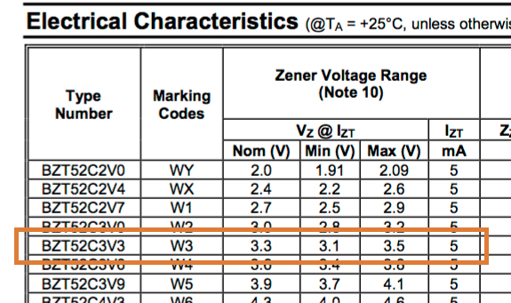
An example is this 3.3V Zener from Diodes Inc (at Digi-Key). Looking at the data sheet, it’s nominal Zener drop is 3.3 volts when 5.0 mA is applied. Using a stable 5.0 volt supply, a 340 ohm resistor will give you a stable Vout of 3.3 volts. Keep in mind this isn’t a voltage regulator. Well, at least, not one that can provide much current.
Use it for the analog reference
Let’s say you have an 5 volt Arduino measuring the 7.4 volt lithium polymer battery pack from the first example. Attaching this circuit to the AREF pin will increase the resolution of the A/D converter. The full-scale range of the A/D is no longer VCC’s 5.0 volts. Instead, it will be the lower 3.3 volts. Why 3.3 volts? Well, I picked it as an easy to buy Zener. And to measure the battery with an Arduino, you’ll need to divide down anyway. So here you’ll do something like a 2.3:1 divider. For slightly better resolution you could use a 3.7 volt Zener, if you can find one.
#4 R-2R Ladder
An R-2R ladder is a bunch of repeating resistors, or a network of resistors. The idea is that as you turn on more inputs, it affects the output voltage. This circuit is one way to make a digital-to-analog converter (DAC). You apply digital inputs and get an analog voltage out. Since this is a form of a current divider, the performance depends on how well the resistors are matched to each other. So you should use precision parts or measure each to match them manually.
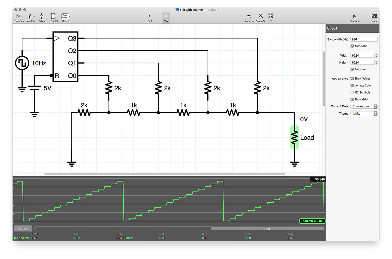
Add more resistors to the string for more resolution. Use better matched resistors for more precision. In this example with 1K and 2K resistors, each bit is worth 313 mV. The max output is 4.68 volts. I might cover these in more detail in the future. For now, check out this great Tektronix blog post on R-2R DACs.
#5 One Analog Input Button for many Buttons
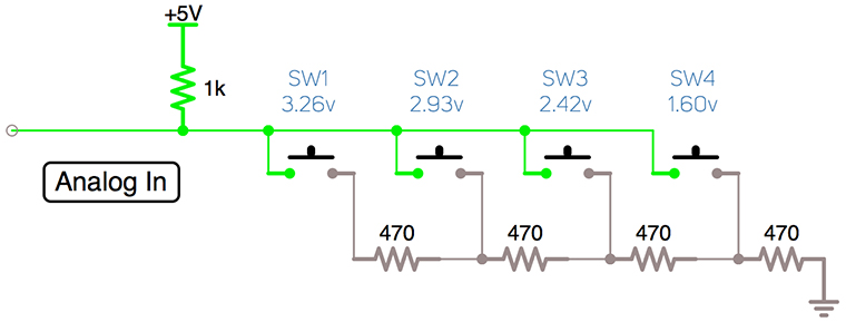
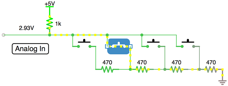
Using a network of buttons and resistors you can use a single analog input for multiple buttons. Between each button is a resistor value. In this example, I used 470 ohms resistors. When you press a button, R1 (1k) creates a divider with the rest of the network.
Here I am pressing button two (2) which means the voltage out is a divider between 1 Kohm and 1.4 Kohm. You don’t have to use equal resistor values. My suggestion is that you pick values that give you a wide range between the buttons. That way your code reading the analog input can have a wide input range.
By the way, to check a range in C/C++, you need to use a logical-AND statement. So for example, reading A0 on an Uno might look like this:
int analogValue = analogRead(A0);
If ( (analogValue > 128) && (analogValue < 512) )
    // Do something… it's between 128 and 512.
Conclusion
Voltage dividers have a variety of uses. As you might notice, nowhere on this list is there a “voltage regulator.” The Zener reference comes close, but that circuit isn’t designed to drive much current. Or at least, not current to a load that might change.