When your project needs a transistor, there are tons of choices. Which makes answering the question “Which transistor should I use or buy?” a daunting task. Fear not, before wading through spec sheet after spec sheet, consider one of these four general purpose transistors. Every electronics enginerd’s toolbox should have a few of each.
Transistors are one of the most versatile discrete components in electronics. In digital circuits, they switch on and off while in analog circuits they are used to amplify signals. For most projects, they are used to turn on a load that would kill the I/O pin of a microcontroller or microprocessor. For most circuits either a BJT or MOSFET can be used, depending on the load current you need to switch.
[Edit Note] Jan (comment below) points out that there are European Equivalents that may be more available for those located in that part of the world. For NPN Check out the BC547, for PNP the BC557.
Here are some more details on each of these.
Best Transistors: BJTs
Bipolar transistors come in small packages, can be driven by I/O pins directly, and are VERY cheap. There are two variants, the NPN and PNP. These little guys are the workhorses of most control circuits, for small current applications. You’ll commonly find through-hole parts in the 3-pin TO-92 style package.
#1 NPN – 2N3904
You can find most often NPN Transistors in low-side switch circuits. This configuration means whatever you want to control is connected between the “high” voltage and the collector of the transistor. Check out this post for more information on low-side vs. high-side switches.
A common transistor I use is the 2N3904. You can easily switch big, like great than 12 volt loads with this transistor’s max 40 volt rating. Its current rating is only 200mA, but that is enough for most relays.
#2 PNP – 2N3906
For high-side switch circuits, you need a PNP style BJT. A high-side circuit is where the load sits between the transistor’s collector and the circuit’s ground. Its emitter connects to the “high voltage.” Since I recommended a 2N3904 for the NPN, I will suggest its complement: the 2n3906. Like the NPN, it has the same max voltage and current ratings: 40V and 200mA. Check out this post for more information on low-side vs. high-side switches.
#3 Power – TIP120
One of the advantages of BJTs is that they are easily driven from an Arduino or Raspberry Pi I/O pin. When configured as a “Darlington pair,” they can provide significantly higher current capability than single transistors. The TIP120 is a Darlington pair that can handle as much as 5 amps when in a TO-220 package. You sometimes see the same package used for LM7805 linear regulators. If you want to drive that much current, do not forget the heat sink!
Best Transistors: MOSFETs
When you have to drive many amps of current, MOSFETs are fantastic. However, most do not work at “logic levels,” meaning they typically need 10 to 15 volts to switch them on properly. Such a high voltage is tough to reach for an Arduino’s 5 volt I/O pin, let alone a Beaglebone or Raspberry Pi.
If you are new to MOSFETs, check out my MOSFET video tutorial (scroll to bottom) and this post on dispelling MOSFET myths.
#4 N-Channel (Logic Level) – FQP30N06L
These workhorse transistors have a max 60 volt and 30 amp rating. Not milliamps. Amps! (Though, you will need a heat sink!) They cost nearly 2X what a TIP120 costs, but they drive way-way more current. The best part? With a “logic level” compatible Vgs-threshold, an Arduino can easily drive them with its 5.0 volt output pin. These properties are why I keep a pile of FQP30N06s on hand.
Conclusion
These four general purpose transistors will cover a wide range of uses. Having a couple of each in your box will come in handy for nearly any project. Leave a comment below on which transistors you keep on hand.


72 Comments
Thanks baldE, very helpful. As a hobbyist, i have had a lot of success with the the 2n 2222 bpj in oscillators and in low voltage switch circuits.
i can use lot help on taking parts and already circuit boards and how use change them for what i need them for along the lines of variable current and volts power supply’s and ect.
very informative
• I advise and like the following:
a. BC547 NPN Small Signal (Fmax 100MHz | IC 100mA | VC 45V)
b. BC557 PNP Small Signal (same as above)
These are the best two transistors based on price and performance. I have at least 5K of each in stock.
☆Thank You For Reading☆
I think your suggestion to have “a couple” of those on hand is pretty optimistic for people like me, who sometimes forget that a current-limiting resistor is a REALLY good idea 😀 Good thing they’re cheap!
Hello James,
Trying to fix a treadmill control board providing power to a 120 VDC variable speed motor.
Found a BJT on the board with it’s (flat) face completely blown off so can’t make out the markings to buy the replacing transistor (there is only a 9 shown on the curved side?).
Assume the BJT is 1,2,3 (left to right) while looking at the flat side.
Also, BJT seems to be supplied with the selected control speed PWM voltage (V) which ranges from 25 to 30 V based on selected treadmill speed.
Board traces as follows:
Pin 1: Supplied by PWM voltage V but first has 2.2kohm and 1kohm resistors in series before reaching pin
Pin 2: Supplied by same voltage trace V but only goes through the same 2.2kohm resistor.
Pin 3: traces downpath to reach/control IRFP250 MOSFET gate pin which directly controls VDC to the motor
My question:
What is the most likely BJT that would be needed to replace the blown one?
Many thanks –
Thanks for the info. I stock mostly 2N4401, 2N3904, 2N2222, & BC549C. I also have other odds & ends.
Loved your article. I have by my side some 2n7000, do you know a transistor available which is the p type of the 2n7000?
I did a parametric search and found the Vishay TP0610K. Though, through-hole packages seem to be lacking.
I’d suggest the IRL2203, which has 10mOhm on resistance at 4.5V gate voltage. When conducting 30A, it only dissipates 0.3W, which will raise its temperature to about 20C above ambient. No heatsink required.
what about the current limit in 2n2222? can this 2n2222 only carry 125 mA or the overall 6.125A?
Please read the datasheet for the 2n2222. It will list an absolute max for the collector current, or Ic. “Absolute Max” is where damage occurs, so you should operate about 20% below that number. I will at least tell you that it is well below 6 Amps.
Hi Manuelito, I think this video may help you: https://www.youtube.com/watch?v=8DMZSxS-xVc
what i am trying to build is a shotclock using arduino as its microcontroller, this contains about 49 segments of led strip and each strip has a rating of 12v,1.5 watts now i am not sure if this 2n2222 has enough rating if i use this transistor in each segment and by only using a single 12v dc source witihin the ckt of this 2n2222 of course the arduino will only look like an actuator like a relay but my problem if i only paralleled all these segments(different 2n2222) in a single dc source
Sure, you can do this with a single 12V supply. 12V at 1.5W = 125 mA per segment, x 49 segments = 6.125 Amps. 49 segments / 7 per digit = 7 digits. So when the display is using the most current, 888888 , the required current is 6.125 Amps, so you need a 12 volt supply that can deliver at least 6.125 amps. I would target at least an 8 Amps supply so that there is some safety margin.
what im going to do is to power up a shotclock using arduino as its microcontroller but each bar of the 7 segment has a power rating of 1.5w,12v if i use this 2n2222 for each digital output of the arduino to power up each segment and all of these segments were just powered up by a single dc source will it still work fine?
What about IRLZ44N? It is also a logic lovel power mosfet, with even lower resistance RDSon (only 0.022 Ohm), ad rated for 55V and 47Amps!!!
Keep in mind that Vgs is the minimum voltage to start turning on the transistor. So at 2 V, the rated minimum, you cannot get the full 47 Amps or an RDSon of 22mOhm. It is still an impressive MOSFET and one worth considering. With a Vgs of 3.3 volts, you could still pull 10-20 Amps through it.
Thanks you so much for suggesting IRLU024N. I was looking for something I can source locally here in US. Got 10 of these on Arrow.com for $3.8, next day air delivery!!
i want to make power public address amp but i don’t no which type of transistoris best
My 2n2222 is over heating. My power source has 3A 4v
I think 2n2222 is able to hold only 800milli amps of current & your source is exceeding that.
Absolute max is around 600-800, depending on the datasheet. Absolute max is when damage occurs. So it should be operated below that, which to me a safe operating area is like 500mA.
Without seeing a schematic, it isn’t possible to explain what is wrong. It’s only rated for about 500mA. So if you’re trying to run more current than that through it, that’s the problem.
Many micro controllers use 3.3 volt instead of 5 volt.
I’ve been searching around but could not find a logic level MOSFET which worked with 3.3 volts.
Do you have any suggestions about how to solve this?
For use at 3.3V I like the AO3400/N-channel & AO3401/P-channel both of which are spec’d down to 2.5V. If nothing else you can use one of them to easily control one larger MOSFETs.
Yes, I know it’s over a year old, but did not see an answer.
hi what would be a p channel counter part for FQP30N06 thanks
Hi, I need to Drive a 12volt Led panel ( having a total of 32 leds in it ) ,it consumes 140 mamp current ,now i need to drive it by raspberry pi GPIO ,so can you recommend which bjt or MOSFET shall I use to drive it properly.
Thanks
140 milliamps sounds low, but I’m not familiar with LED panels. Any of the transistors on this list are fine.
I would like to build a Microprocessor from discrete transistors. Would look like the Monster6502. I decided to go for CMOS logic. Which transistor are best suited? My search resulted that many transistors are designed for high power, which is not the case with my processor. And thus they are usually more expensive. I found the FDV303N and FDV304P transistors by Fairchild. But they are SOT23 and therefore too tiny for soldering by hand, I fear.
PS: I didn’t examine the electrical charecteristics yet. Will it do soon after watching some of your videos 😉
I cannot suggest a transistor. I have never tried such a project. I would try contacting Eric and ask what he used on his 6502.
SOT23 are big enough for hand soldering, even with a fairly cheap iron (I often use an old Antex at work). I’ve been soldering smaller packages at work for over 10 years, including 0402 passives and 0.5mm pitch semis, but many of us need magnification – even an illuminated magnifier should be plenty for SOT23 and 0805 or 0603 passives, a stereo microscope if you plan to go smaller. I haven’t been able to persuade my boss that I do enough rework to justify something like the Mantis Elite or a digital equivalent – should you decide to go down the SMT route and get any sort of microscope, remember that working distance needs to be greater than most microscopes are designed for, and investing in a lens cover to keep crud from condensing on ithe lenses will save you much pain.
The trick with SMT is to add flux first – the 24/26 gauge solder wires don’t provide enough, and it helps to hold the component in place. The solder you add to the joint will probably be enough for 3 or more joints on a pre-tinned PCB, dragging the tip along a row of components and they are all soldered was awesome the first time I saw it, when moving from through-hole components.
Thanks for you article. I am curious what you would recommend for a jfet. It seems that the j201 is the most popular choice, but it’s limitation of 50ma leaves me to wonder if there is a better choice ?
What I am using it for:
I believe I need to use a jfet for a robot project. The motordriver (Sabertooth) e-stop signal line connected high (+5v) will allow the motors to operate. Removing the +5v (line is pulled low) will stop the motor driver.
I have an e-stop button connected to to ground, and need to use that to break the 5v e-stop line (+5 to signal input). I am planning on using the j201, but am wondering if there is a better way to connect my “e-stop push button”. Thanks
First, JFETs are usually used for analog circuits. They are a good alternative to BJTs. (Are you confusing JFET with MOSFET? JFET is a type of MOSFET.) You typically wouldn’t use one in a switching application. An “enhancement mode” MOSFET is a better choice. Second, for an e-stop, I don’t understand why you would use a transistor at all. An e-stop switch is usually wired in at the main supply voltage. They are used to directly disconnect power in an emergency. I don’t know of any other way to wire one except at the supply.
If you’re using an e-switch to enable or disable a transistor, that is a very bad design choice. In the event the transistor fails shorted, your e-switch may do nothing. That creates a huge safety hazard.
Excellent, Thanks so much for you quick response. Agreed, the e-top would be best with a SPDT push-button type switch. The +5v line would be connected to the normally closed push-button connected to the signal line. Pushing the push-button would open the circuit – signalling the motor-driver to stop. I wanted to use a small SPST push-button wired to ground to trigger a transistor to open the circuit (Thus the JFET).
I thought the JFET would open a circuit when triggered LOW.?
I will have to read up on the “enhancement mode” MOSFET. I have not heard of that. Thanks 🙂
Watch this video on MOSFETs: https://www.youtube.com/watch?v=GrvvkYTW_0k.
Thanks, This is great stuff! I think the TO-220 will do the trick. Wish I could post schematics or pictures here – But you pretty much cover the answer in the above supplied video… Anyone want to buy a handful of useless JFET’s that I just bought – lol 🙂
For NPN I prefer 2N2222, for PNP 2N2907 , For power transistors, 2N3055 NPN or MJ2955 PNP, as mosfets IRF3205 55V 110A mosfet, IRFB4110 100V 180A mosfet and IRF2804 40V 280A mosfet.
Yep, I think the PN2222A and 2N2907 in to18 and to92 are the best, I use them all the time.
James, you hit right on the money with this article…incredibly useful information.
Those 4 transistors are super awesome to have in stock on the bench. I can’t tell you how many times I’ve used the 2N3904. For higher current, the TIP120 is hard to beat as well.
Another great general purpose NPN to have on hand is the PN2222A. They are super cheap and incredibly useful: from turning on fans, relays, or even higher power LEDs.
Keep up the great work and thanks for the article.
Mike
how do this 2n2222 differs from TIP120? is this 2n2222 has enough rating to power up a 30+pcs. 12v ,1.5w led strip through my arduino?
1.5 watts at 12 volts is 125 mA. The 2n2222 has a max collector current of about 800 mA, so should be kept around 500 mA. While the TIP120’s max is about 5 amps, so it should be kept around 2 or 3 amps. Since both are significantly more than 125 mA, either would work fine.
will it still be fine if i parallel a 30pcs of 2n2222 to a single 12v dc source having a load of 1.5w led per pc.?
That sounds like you have 30 LED strips, each 1.5W. If you are trying to turn them all on with a single signal from your Arduino (30 * 1.5 W = 45 W total) it sounds like you would be far better off to use a single 2N2222 controlling power to a relay, and use the relay to switch the power to the LEDs. If you want to control each 1.5W LED strip separately, then as James said, it should be within the capabilities of a 2N2222 per strip.
But this assumes you are turning the LEDs either full on, or off. If you are trying to control intensity by PWM, then the relay won’t work (not fast enough), and the continuous swiching of PWM may lead to a 2N2222 to over heat.
Maybe we need more details of what you are actually trying to do, to better help you.
Hay all you guys out there wanting a list of parts to keep in your work bench parts bin this is a big list but you can pare it down. Maybe some one will do that and post it here (wink wink ).
http://forum.allaboutcircuits.com/threads/components-selection-guide.65137/
This was a brilliant article. Any chance you could do an article on the top 4 or 5 capacitors to have on hand?
really helpful … thank you very much !!
I am currently in the beginning stages of learning how to repair amplifiers and only problem I am having is identify the wrighting for direct part replacement . This is part number I am needing bad. But no luck. 80nf70 /czod T /Mar 247/.that’s all I see on side of 3 leg fet. If you could help i sure thank you
STMicroelectronics marks their “STP80NF70” MOSFET with a “80NF70” marking.
https://www.mouser.com/ProductDetail/STMicroelectronics/STP80NF70?qs=%2Fha2pyFadugyCCEaphAVGt7DDNknOLNw%2FvvTxrp%2FOVk%3D
https://www.mouser.com/datasheet/2/389/stp80nf70-956554.pdf
Would you know the equivalent of Ss8050 D331? Thanks
Sorry, I don’t know what that is.
LOL, obviously a transistor. Don’t worry about it.
http://www.mouser.com/ds/2/149/SS8050-117753.pdf
HELLO MY FRIEND! could you help me….
l would like to ask you for a type of transistor that can switch up a consumer of a 2A 3v by a digispark pin of a 3.3 v !
the supplier for the both of them is a3.7 lipo !
it is for model of airplane so I need a smd transistor and a “regular” too but a small or light one !
Thanks in advance
I would try a distributor’s website for that kind of search. For example, on Mouser.com you should be able to put in the parameters you want to get some options. (This is useful even if they do not ship to your country.)
thank you !
Great list… I also like to keep some trusty 2N7000 parts for general purpose switching at my bench.
I’m curious if you have a similar list for op amps…
Not yet, but good idea.
HELLO … ! you have a great site !!
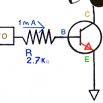
i wanted to ask about BJT tutorial – you finished of a saying that the transistor is forcing to current from the co. to emi. to be 100 mA , and you get 6 v battery , then I’m not understand – what now this circuit got forced to be in v and I and what is the analyse that i do now for enter another consumer than a motor , lets say another motor (my motor don’t have any v properties , i just found that it draws between 60 to 200 mA on 5 v ?
Current is not forced at any time. Current is allowed to flow. The “beta” of the transistor is the ratio of current between Base/Emitter and Collector/Emitter. If the transistor has a beta of 100, and the current from the Base to Emitter is 1mA, then up to 100mA will flow between the Collector and Emitter. Beta varies from transistor to transistor and it varies depending on the amount of current flowing (which makes it sometimes difficult to predict.)
thank’s for the quick answer !
re: FQP30N06L “They are “logic level” compatible and can be easily driven from 5V! ”
But can they be driven from 3v such as from Raspberry Pi i/o?
Yes.
The max Vgs is around 2.5V. Even if you get one that’s pegged to the Max, it’ll at least turn on the FET even if Rds is a bit higher than usual.
For NMOS driven by 3.3V (1.8V also), smd package, I’d use Si2312 [email protected]
VGSth=0.8V, Ciss=740pF IDSmax=4.2A.
We should use these when the in/out capacitance is not a problem. In my current project, I need very small capacitance between drain/collector and source/emitter, SOT-23, so I’m limited to a NPN BJT instead.
MMBT2222, BCW66, BCX19 all look good.
Notice that the current gain of BJT depends on the target Ic. For my design, Ic would be 150mA, hence the above devices are suitable.
I also recomend SS8050 or S8050. Can handle upon 1.5A in a TO-92 Packaging. Here in Mexico are even cheaper than 2n3904.
Hi James,
very common in Germany is also the ULN2003, 6x 500mA/50V Darlington.
BUT it’s not 3.0A in total
http://www.farnell.com/datasheets/1690348.pdf
Thats a good list!
The european versions of the 3204 and 3906 transistors are like the BC 547 and BC 557. These are most common here (theres a huge list which compares BC and 2N types)
Anyway I´d like to add the BS170 low power mosfet to the list. I use it all the time instead of a low power NPN. Not logic level but have a look at the datasheet, DS-resistance is low enough @5V gate voltage…
The two high power logic level mosfets I always have at hand are:
IRLU 024N (55V, 17A; cheap and SMALL PACKAGE)
IRL 3803 (30V, 120A; quite expensive)
Your description of #1 is a Low side switch, not a high-side switch.
Look at Linear Tech data sheet for LT1089. It shows an NPN with collector tied to the positive rail, and the load is from emitter to ground.
Have a look at the block diagram for LTC4446. Control of the transistor that is connected to the positive rail is the high side, the transistor that is tied to ground is the low side.
Opposite mistake on #2. Your description is a high side switch, not low side.
Thanks for #4, good find.
Yes, you’re right. I got myself mixed up. This isn’t the first time I made this mistake… It’s been fixed.
Thanks.
I’m looking at my comment of april 2014, and wondering what is the ref to $4??? After thinking about it, it must be a misspront. I meant #4 🙂
Oops! Like facts on Wikipedia, that is easily changed. 😉