Category

Electronics Basics

Category

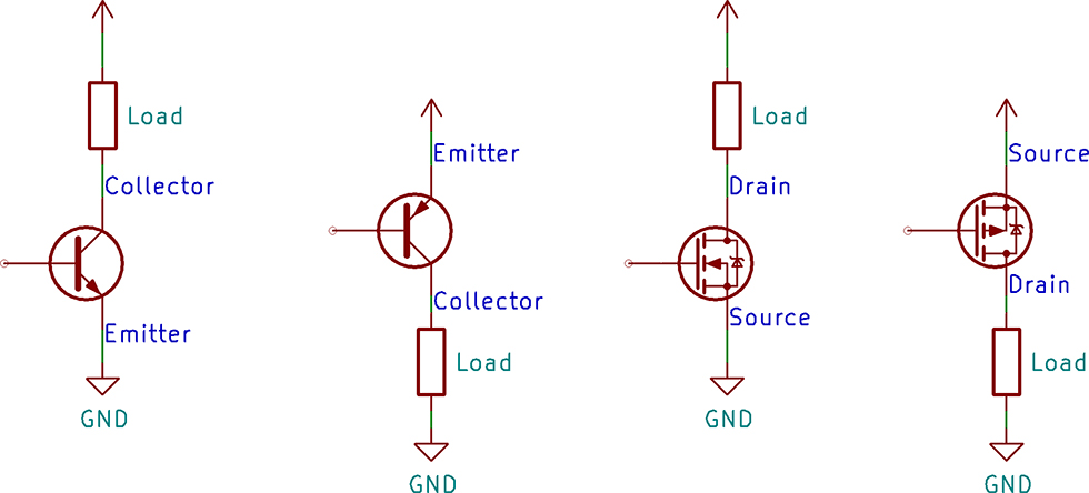
A common task for a transistor is switching a device on and off. There are two configurations for a transistor switch: low side and high side. The location of the transistor determines the type of circuit and its name. Either transistor configuration can use a BJT or MOSFET.

In this post, I draw the configuration for both transistor types, discuss which requires a driver, and explain why you would use either. If you are new to transistors, check out the resource links at the bottom. I have a few videos I made and some from element14’s The Learning Circuit, which do a great job introducing transistors.

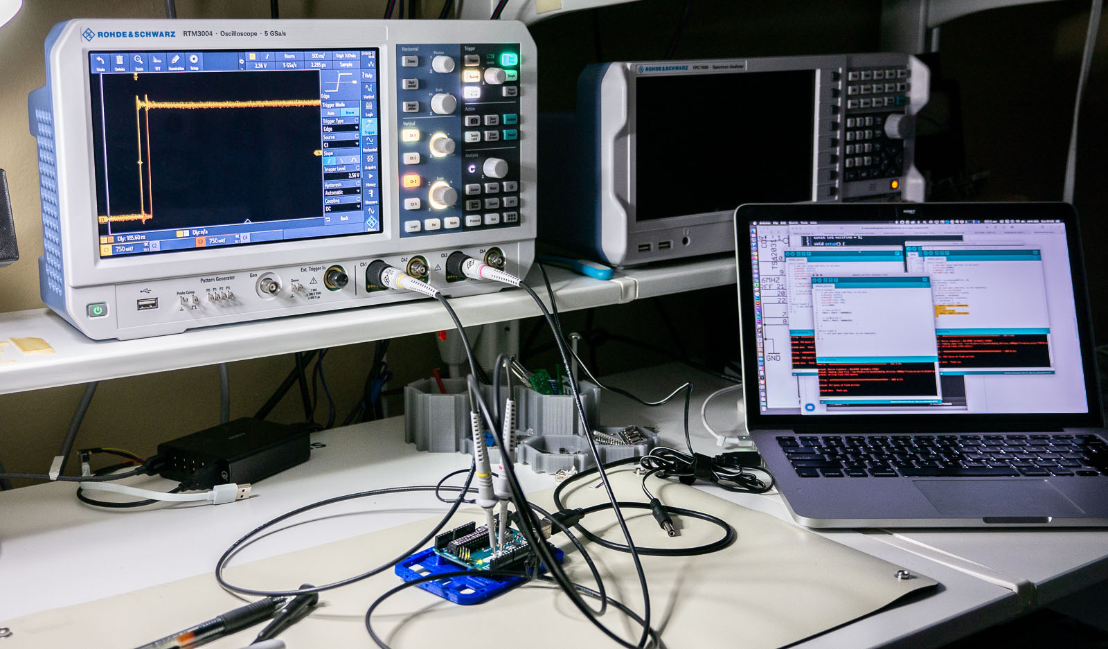
One of the best ways to learn how to use a new piece of test equipment is to use it. Sounds easy, right? The problem is, sometimes when you are in the middle of troubleshooting your circuit, figuring out what the knobs on your scope do is an immense frustration. Use these 6 oscilloscope measurements, and just an Arduino Uno, to learn how to use a new or unfamiliar digital scope.

This tutorial is not a step-by-step guide on how to make each of these measurements on a particular scope. Instead, it is a general explanation on how to setup the Arduino and a screenshot to help identify if you set up your scope correctly. I reference the R&S RTM3004. However, practically any two (or more) digital channel oscilloscope should work.

Between each measurement, I highly recommend using your scope’s default setup (or autoscale) before proceeding to the next one!

As a kid, I got the book “Upgrading and Repairing PCs.” (Now in its 22nd edition.) It was the first book to explain to me the PC architecture. I considered, how were there so few pins on an AT-style keyboard connector when there were 101 keys on the keyboard? That is when I first learned about the keyboard matrix.

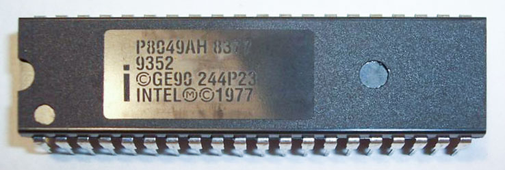
Intel_P8049_AH_controller
Original image from Deskthority Wiki. (Edited image is shown.)

The keyboard matrix itself did not amaze me, but instead the idea there was an entirely separate 8-bit microcontroller inside of the keyboard. Early keyboards may have used the P8049AH, which, there is still some stock available to purchase. I was fascinated with the idea an entire computer was necessary to run the keyboard, to use my “real” computer. Why did it take something as complicated as a microcontroller?

Can you use voltage dividers as regulators? What if you add a Zener Diode? In this AddOhms episode, I show what happens when you try to power a complex circuit like an ESP8266 with a voltage divider instead of a regulator. (Spoiler: Get a voltage regulator.) This video tutorial is related to a write up I did recently on Zener Diodes. For questions or comments visit the AddOhms Discussion Forum.

Behind the scenes

A significant change for this AddOhms Episode is that I moved from Final Cut Pro X to Premiere Pro. I also shot the entire video in 4K, even though the output is 1080p. Animations were still done as 1080p compositions. One snag I ran into, the color corrections I applied in PPro, didn’t seem to get exported. You might notice when the breadboard is on screen, it has a very slight yellow tint to it.

I’ve been changing how I produce the videos. It’s shortening the cycle time. The key is that I’m not trying to animate every scene. The amount of work involved is just too much. I animate practically every frame. So in a 6-minute video, that’s just too much.

By the way, there are two easter eggs in this episode. Can you find them?

Voltage Dividers as Regulators on YouTube