")
Continuing the DIY Arduino tutorial series, this AddOhms episode shows how to create a PCB in KiCad. I make a joke that the original design was a rectangle, which I found boring and pointless. So instead, I designed a triangle to give the board 3 points. Get it? Puns! I am calling it the Pryamiduino. To be honest, I found not having a constraint to be a problem. By forcing a specific board size and shape, many decisions were more manageable.
In the end, the video ended up more edited than I planned. KiCad is just so finicky and crashy that I could not make a coherent start to finish tutorial. At least, I could not work with a board at this level of complexity. Something simple like a 555 flasher would be easier to show from start to finish. I am planning some immediate follow-ups with quick tips on using KiCad. It is a frustrating suite of applications, but the results can be quite nice.
AddOhms Pyramiduino Show Notes
Changes from Episode #23
If you are following the series, just a quick note about changes in the original schematic.
- In the video, I selected a 4-pad normally-closed button. At the very end, I replaced it with a normally-open. As a final replacement, I used a 2-pad schematic symbol.
- I changed the crystal’s symbol and added a 16 MHz value. The new symbol had ground connections, which are also available on the component I am using.
- There was confusion on whether DTR or RTS was the right signal. Historically I connected DTR. However, on my FTDI board it has RTS broken out, so let’s stick with that name.
- I simplified the capacitors for cost reasons.
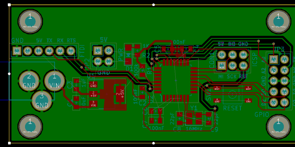
In this video, I then created a modified schematic where I removed the barrel jack. I changed to a 3.3 volt regulator, which is different from the original NCP1117. (I have these other ones laying around.) As shot, the schematic was missing a power LED for most of the video. It wasn’t until the sixth version I re-added the LED. And I decided to hang it off the 3.3 volt rail. This choice lets me know that both 5.0 volt and 3.3 volt rails are up.
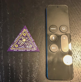
Lastly, the most obvious change, I broke out ALL of the I/O pins you’d find on a Nano. (Originally I only had five digital and five analog pins.) These extra pins give the board its characteristic look.
Behind the scenes of Pryamiduino
I thought this video was going to be a quick one to shoot. Do some voice over, say some things on camera, and screen capture the design. In the video I say I built the board five times, that is not an exaggeration. By the end of the video’s recording, I re-drew the schematic at least three times and re-drew the PCB 6 times. (Once more after I show the on-camera stuff.) However, I am happy with the results.
Adobe Premiere, and After Effects pushed my computer to its limits. I rebooted my computer more times this past week than I have the past year. In the future, I hope I learn a better workflow because something I am doing irritated After Effects. (All of the green screens rendered in real-time during editing. I should have made an intermediate render.)
That said, I am quite proud of this video. Doing a “PCB design video” is not easy. Making a “PCB design video” remotely interesting to watch is difficult. Almost as tricky as watching it. While not a tutorial, I sincerely hope there are enough tips and process ideas to help someone trying to draw a PCB in KiCad.
That said, if you did not catch my after credits message, I have two versions of the PCB on the Github project. One is complete and (nearly) identical to the R4 board I sent to OSHPark. I also included an “exercise” version which has two airwires, or rats or unconnected nets, left. Can you find them?