A question came up on IRC regarding how to PWM a 3-pin PC fan with an Arduino using analogWrite(). Controlling the fan was seemingly straightforward. The problem was that the hall effect sensor, or TACH signal, was incredibly noisy. The noise made it impossible to measure the fan’s rotation. Working through the question, I found three issues to tackle:
You need to use a PNP transistor
Filter capacitors help
Create a non-blocking RPM measurement (with millis())
This post addresses all three issues regarding how to PWM a 3-pin PC fan with an Arduino.
1. You need a PNP Transistor
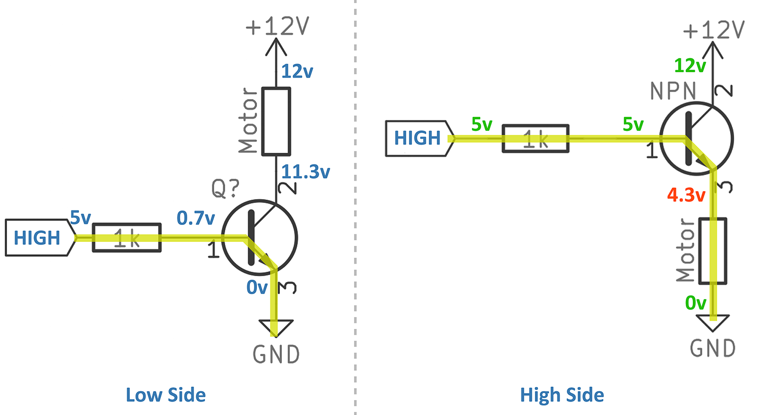
Most tutorials show an NPN transistor driving a motor as a low-side switch. However, the problem with this approach is that you are switching the ground (GND) path. This method doesn’t provide a return path when the FAN is turned off. Regarding the fan’s operation, it will turn on and off as you expect. However, the lack of ground path means the switching can create electromagnetic interference (EMI).
Figure 1: Don’t do this!
The proper way to power a fan is with a high-side switch. This circuit type switches the high voltage on and off, instead of ground. But you can’t use a NPN. Figure 1 shows the problem. When configured as a high-side switch the voltage from across VBE remains 0.7 volts. Which means if there is 5 volts at the base, you only get 4.3 volts at the collector. You were probably expecting it to be 11.3 volts, weren’t you? Well, that’s not how a NPN BJT works.
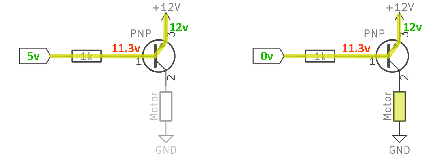
Instead, we can use a PNP transistor for the high-side switch. This circuit does present a problem when using 5 volts on the base and 12 V on the emitter.
Figure 2: Oops. 12V rail with a 5V control.
So the problem is that when the I/O pin is HIGH or LOW, there isn’t enough voltage to turn off the transistor. And you create an awkward voltage divider between the I/O pin and the base of the transistor. If you looked at the collector (shown as pin 2 in this diagram) on an oscilloscope, you’d see it stay a steady DC voltage. Not very useful is it?
To solve the problem of how to use a PNP transistor with an Arduino, you need to add an NPN driver. It seems kind of silly doesn’t it? Well, doing things right isn’t always easy. Or something to that effect.
NPN-PNP Driver Example
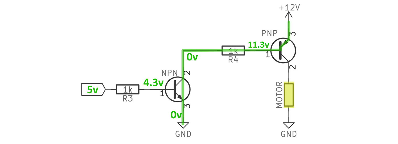
If we add a NPN transistor before the PNP, it can be used to switch the high-voltage supply on and off. This driver would allow the PNP’s base to see a wide voltage range. The NPN can pull the PNP’s base, with its current limiting resistor, to 12 volts. This mode will prevent 0.7 volts from dropping across the Base-Emitter diode keeping the transistor OFF. When the NPN drops to ground, then VBE becomes active, and the transistor turns on.
Figure 3: I/O Pin is HIGH, Motor is ON
In Figure 3, I’m showing what happens with the NPN-PNP driver when the Arduino drives 5 volts. It turns on the NPN, which connected the PNP’s base resistor to ground. This path allows 0.7 volts to drop across the PNP’s Emitter to Base junction. The transistor turns ON and the motor spins.
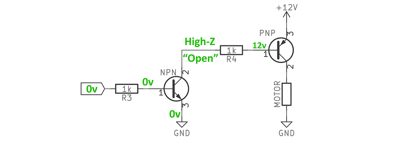
Figure 4: I/O Pin is LOW, Motor is OFF.
Now, when the I/O pin goes LOW, something more interesting happens. The NPN turns into an open because it’s Base-Emitter junction is off. So that leaves the PNP’s base resistor floating. So that means if there is 12 volts on the Emitter, that is the anode of the junction diode. Since current can’t flow through the NPN, the cathode of the junction diode is effectively floating, meaning it will show the 12V connected to its anode. So the VBE becomes: 12v – 12v = 0v. This relationship keeps the PNP, and the motor, OFF.
2. Filter Capacitors Help when you PWM a 3-Pin PC fan with an Arduino
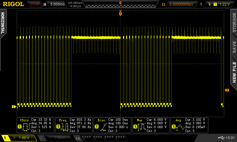
Once this was all setup, I connected my scope and saw the following:
Figure 5: Noisy RPM Signal with PWM
All of the noise spikes shown are finding their way into the I/O pin. It falsely triggered the interrupt, messing up an RPM measurement. So what’s going on here? Where are those spikes coming from? The spikes are EMI from high frequencies in the PWM signal.
But wait, the PWM signal from the Arduino is only about 600 Hz. That isn’t very fast. The 600 Hz isn’t our issue. Instead, it is how fast the PWM signal switches from OFF to ON.
EMI comes from the Edge
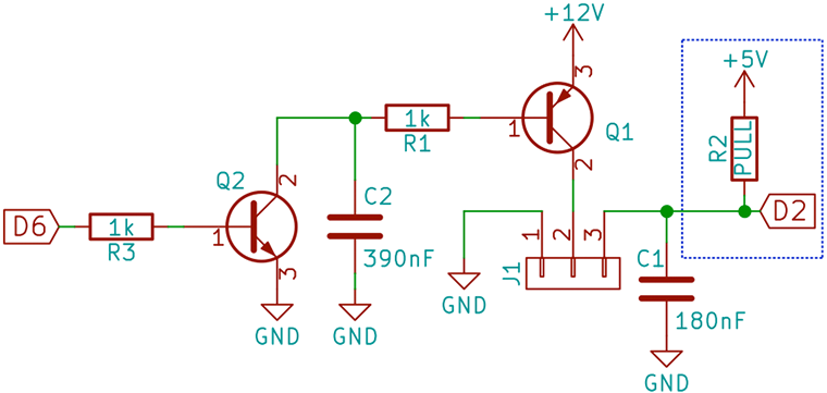
The edge rate from the Arduino I/O pin, and the NPN connected to it, transitions from LOW to HIGH incredibly fast. There is a lot of what we call “high-frequency content” in that edge. That’s what is making its way onto the hall-effect sensor. All of those little spikes are EMI noise. A simple solution is to slow down the edge to the OFF to ON transition. Connecting a capacitor from the NPN’s collector to ground slows down the edge into the base of the PNP. The current limiting resistor (R1) and capacitor (C2) form an RC network, which reduces much of the noise.
Figure 6: Final Arduino PWM PC Fan Circuit
Picking the PWM Filter Capacitor
Normally you could do a bunch of math to figure out an ideal resistor-capacitor combination. In my case, I just connected a 390nF Ceramic capacitor for C2 and all was good. I did look at using a 470nF and 1uF electrolytic capacitor. However, those had enough capacitance to even out the voltage creating a constant ~10V, preventing any switching. Additionally, their ESR causes substantial “shelves” to appear on the edge. Stick with ceramics or film capacitors for this type of filtering.
Depending on your circuit, you may need to play with that value. Basically, make it big enough to reduce the noise spikes, but low enough that the NPN can still switch the PNP off.
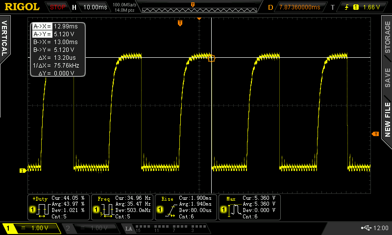
You’re probably going to want a scope for this measurement.
Figure 7: Multiple Cycles from Hall Effect
The hall sensor is still a bit noisy, especially on the rising edge. The falling edge is pretty clean. So even though this signal is active HIGH, I decided to measure the falling edge. I did find adding some additional capacitance on the sensor signal helps clean it up a bit more. You could also consider playing around with an external pull-up resistor to for a similar RC like filter.
With my PWM signal driving working well and the hall sensor signal cleaned up, it was time to measure RPMs on the Arduino.
3. RPM Measurement with millis()
I created a simple serial interface (single character commands) to adjust the PWM speeds. There is a one-second interval used to display current RPM. The interrupt is used only for counting pulses from the hall effect sensor. However, I don’t think even that is necessary. (Maybe something to tackle in another tutorial.) RPM calculation is pretty basic, but seems to work. My fan is rated for 1200 RPM and I’m measuring 1250ish. The slowest I can seem to run this fan is 600 RPM.
As usual, no delays means you can easily incorporate this code into other Arduino sketches.
unsigned long previousRPMMillis;
unsigned long previousMillis;
float RPM;

unsigned long interval = 1000;
byte pwmValue = 125;
byte pwmInterval = 5;
const byte pwmMax = 255;
const byte pwmMin = 0;

const int reedPin = 2;
const int fanPin = 6;

volatile unsigned long pulses=0;
unsigned long lastRPMmillis = 0;


void countPulse() {
  // just count each pulse we see
  // ISRs should be short, not like
  // these comments, which are long.
  pulses++;
}

void setup() {
  Serial.begin(9600);
  pinMode(reedPin,INPUT_PULLUP);
  attachInterrupt(digitalPinToInterrupt(reedPin), countPulse, FALLING);

  pinMode(fanPin, OUTPUT); // probably PWM
}

unsigned long calculateRPM() {
  unsigned long RPM;
  noInterrupts();
  float elapsedMS = (millis() - lastRPMmillis)/1000.0;
  unsigned long revolutions = pulses/2;
  float revPerMS = revolutions / elapsedMS;
  RPM = revPerMS * 60.0;
  lastRPMmillis = millis();
  pulses=0;
  interrupts();
  /*Serial.print(F("elpasedMS = ")); Serial.println(elapsedMS);
  Serial.print(F("revolutions = ")); Serial.println(revolutions);
  Serial.print(F("revPerMS = ")); Serial.println(revPerMS); */
  return RPM;
}

void loop() {
  handleSerial();
  analogWrite(fanPin, pwmValue);

  if (millis() - previousMillis > interval) {
    Serial.print("RPM=");
    Serial.print(calculateRPM());
    Serial.print(F(" @ PWM="));
    Serial.println(pwmValue);
    previousMillis = millis();
  }
}

void handleSerial() {
boolean printValue = false;
  while(Serial.available()) {
    switch (Serial.read()) {
      case '+':
        pwmValue = pwmValue+pwmInterval;
        printValue = true;
      break;

      case '-':
        pwmValue = pwmValue-pwmInterval;
        printValue = true;
      break;

      case '!':
        pwmValue = pwmMax;
        printValue = true;
      break;

      case '=':
        pwmValue = 125;
        printValue = true;
     break;

      case '0':
      case '@':
        pwmValue = pwmMin;
        printValue = true;
      break;

      case '?':
        Serial.println(F("+ Increase"));
        Serial.println(F("- Decrease"));
        Serial.print(F("! PWM to ")); Serial.println(pwmMax);
        Serial.print(F("@ PWM to ")); Serial.println(pwmMin);
        Serial.println(F("= PWM to 125"));
        printValue = true;
      break;
    }
  }
  if (printValue) {
    Serial.print(F("Current PWM = "));
    Serial.println(pwmValue);
    Serial.flush();
  }
}
Conclusion
While this was a fun academic exercise in the proper way to switch motors, it really wasn’t necessary. This entire tutorial is based on a 3-pin PC fan. If you buy a 4-pin PC fan, the 4th pin is for PWM control. The filtering has already been taken care of in that fan. So while this works, it isn’t necessary if you buy the right fan at the start.
Fan of making things beep, blink and fly. Created AddOhms. Writer for Hackster.io News. Freelance electronics content creator for hire! KN6FGY and, of course, bald.
Hi, thank you for the article, really helpful. I have just one question. If I lower the analog signal down to low RPM, the FAN starts to return a noisy sound, like coil whining. Any idea of how to mitigate or remove this? thx
Figure 6 – It looks like C2 is on the wrong side of Q2. It’s not an RC filter, but an unprotected capacitor. You’re not slowing down Q2 turn-on if you don’t RC at the Base. You’re shorting out a charged capacitor C2 when Q2 turns on, and not limiting the current through Q2 or C2 when it does (initial state).
For faster PWM signals or more precise duty cycle, a modification of figure 6:
Adding a schottky diode (anode to base on Q2 and cathode on collector on Q2) will prevent the saturation of the transistor and the slow discharge in the base
Hey, I have 10 non pwm fans I got for like $20 that I am using in an array to control i/o air from my server room. I am planning on using basically the identical design to yours with all 10 fans in parallel. Will this work? I have on hand BD139s and various PNP transistors as well as 1N4007s. Due to the high frequency my breadboards are no good for this, and while I have a scope and such it is still going to require a lot of re-soldering if things dont work out. As it seems you have far more experience than me (I am an electrical student) I ask this: do I need to change anything to run all 10 of these 12v fans in parallel? From what I can tell the transistors will be okay but not positive about that, and also not sure if I should change the values on that filter you have. Thanks for your help!
also, I am not operating via serial, only the same design for the hookup of the fans, I am using LM35 temp sensors attached to arduino to determine pwm level
I made the assumption the built-in motor controller has the proper diodes, since it is highly unlikely a PC motherboard would have had any. That is one of the key reasons a high-side switch is needed.
I bought a three pin ebmpapst 512 F/2 (5’000 RPM), followed Figure 6 (using a 2n3904 and a 2n3906) and used your code on a Arduino Uno and oddly enough:
– I can’t make the fan run at its full speed it seems to max out at 3’056 RPM (PWM: 255)
– And reading RPMs is less stable with the capacitor than without. Without I get a pretty stable 3’056, and when I add the cap, it sometimes jump from 3056 to 3116 and back to 3056
I would drive the fan directly, without the transistor, to verify it runs full speed. If so, then you could try reducing the base resistor down to something between 100 and 470 ohms. As for the cap cleaning up the RPM reading, without a scope to see what the RPM signal looks like, it is hard to say what is going on. Do make sure the internal pull-up resistor is enabled, as shown in the code.
Driving the fan with 12V directly and read RPM via the third pin, then yes I tried it and it does run at 5034 RPM according to the Arduino.
It’s pretty weird cause I can read the value without the capacitor but as soon as I use a 180nF the Arduino says 0 RPM even though the fan is running full speed. I don’t (yet) have an oscilloscope unfortunately.
Thank you for your help
This post helped me a whole lot. I even went down the data sheet rabbit hole from the load switch link in the other article. Thanks a bunch! I need high side switches controlled by a 7 segment driver to drive 12v high powered LEDs in a display. This should do the trick!
Thank you very much for this interesting and detailed article. I am an Arduino hobbyst and usually i make them for educational purposes. I have faced similar problems at the beginning. But after reading this i suddenly understood it. I am not an engineer sadly an my electronic knowledge is very little. Can i use different types of NPN PNP transistors?
For 12V DC pc fan . Most likely i use BC 547,557.
Can you discuss what it means to be PWM switching a brushless DC motor? I’ve ripped apart a similar fan to peak under the hood and it used a CC6407 chip to switch the coils on my fan. I was able to use a 1khz PWM driver to vary its speed but did not monitor the tach for this. It seems to me that as long as your PWM frequency allows the fan’s IC to operate normally it shouldn’t be a problem, though maybe not particularly efficient.
I guess without being familiar with the specific circuit theres no way of knowing exactly how it will react. I pulled apart a V2 NZXT fan that looks similar to yours to confirm it is indeed brushless. It was a RF-FN122-RB. Inside I found a similar layout with a 2 pole motor driven by an FTC S211.5PF chip. I confirmed a varying speed response with voltage adjustment and PWM. I dont have any good way to measure torque and didnt quantify speed.
Thank you for this article. I quickly put together a fan circuit with an N FET and then realized the tacho wouldn’t be grounded during the pwm off cycle and needs either a PNP for switching or a zener on the tacho, so I looked up how others have done it.
My reason for thinking PNP is different to yours and I’d like to understand why not having it grounded to 0V would cause more EMI, given that it would still be attached to 12V on one end, which I see as “grounded” to a higher potential if you get what I mean. I am also doing DAC and ADC in this circuit and having a clean ground is more important than having a clean 12V.
If the circuit is low switched, wouldn’t the 12v rail also be a path for the energy to go?
How would you suggest separating ground planes without having two separate isolated supplies? Would it be sufficient to use a 3v3 linear reg off the 12v rail to run the microcontroller, with a few caps before and after the regulator, assuming the fan is powered off this 12v rail as well?
How does this high-side dual-transistor circuit compare to just using a Darlington (TIP120, say)? My impression was that Darlingtons get around the post-shutoff issue you mention above by providing a parallel path to ground via a diode, but I’m not 100% sure that addresses the same issue you bring up, nor how it compares in performance (both in terms of EMF and power usage). Would love to hear your thoughts on this!
For this discussion, Darlington is the same as a NPN. While the TIP120 is popular with hobbyist, it isn’t very practical. Modern MOSFETs and BJTs exceed its capabilities, significantly.
I have a 3 pin fan circuit but I am not using the Arduino to generate PWM, I have a 555 timer set to hold a frequency of 25kHz and I can adjust duty cycle. The rpm wire of the fan is connected to my Arduino and I have tried using your sketch and a couple of others and found that the readings at 99% duty cycle are almost correct but as soon as I adjust it seems to be reading the PWM signal (RPM reads hundreds of thousands) noise not the hall sensor. How can I get rid of this noise? My 555 timer output is driving an IRFZ44n MOSFET, I have my 12v supply going straight to the fan and the negative of the fan is going to my drain with source connected to the common ground for the power supply and Arduino. It is for PC fan controller I am trying to build and would like to display RPM.
Before anyone takes any of their time to answer I have completely changed my design, got rid of the 555 timer and changed the PWM frequency of arduino pins up to 31.25kHz (Since I have the RPM working I thought I would not need to use normal fan PWM frequency of 25-28kHz as arduino can now do everything). I found this frequency to give the least noise and most reliable RPM values. noise filtering capacitors of 82nF and 8pF for the transistor and RPM wire respectively (if I go higher on the RPM wire I get a higher value when at low duty cycle). I have used different transistors (S8050 and S8550) but hope this is useful to everyone. I have used the EnableInterrupt library on the arduino so you can have more RPM sensors (as I am building a 4 fan channel and 1 LED channel controller).
Hello James 🙂 , I’m a huge fan of your work (from Tunisia :p ) because it helped me a lot in understanding the basics of electronics. and I would appreciate if you can answer my question 🙂 . So in this article, in figure 3, you placed the fan in between the collector of the PNP transistor and the ground in this high-side switch situation. But in this article ( https://www.baldengineer.com/the-best-4-transistors-to-keep-in-your-parts-kit.html ) you said ” A high-side circuit is where the load is placed between the emitter and ground ” . So can you clear this for me a it more and tell me how to place the pnp correctly ? and thank you 🙂 . PS: i’m using this high-side switch to charge a 6v battery by a 9v input voltage.
Thanks for taking the time to put up the comprehensive article! Very helpfull in researching how to make a fan driver to drive a larger fan at a lower RPM than the host controller accepts. Fiddled with https://circuitdigest.com/microcontroller-projects/arduino-waveform-generator to add a fake RPM output signal to satisfy the host controller and used your sketch and circuit to drive the fan at the desired speed.
Hey Bjorn, I’m currently just starting down this path myself (fake rpm signal to the controller, slower fan for less noise). I don’t suppose your code is online anywhere I could have a nosey at it?
Hi,
thanks for the interesting article. I was wondering what is J1 in the last schema, because I’am not able to understand it only by myself! Thank you!
Hi James, a lil’ question: may you add at the post, or give me here the list of the components have you used for this example? For me It’s gonna be hard to replicate it without. sorry 🙂
A NPN transistor, A PNP transistor, two 1K resistors, wire, a breadboard, and a 3-pin PC fan. I don’t remember what transistors I used, but a 2n3904 and a 2n3906 would probably work, depending on the fan’s current draw.
Hi there, awesome explanation this is just what I need for my project. However I cannot make the fan change speed, it just sits there at around 50% speed. Uploaded your sketch with the serial monitor control and I did nothing. I used a BC548 and a BC747. 100nF capacitor to signal, 330nF Capacitor in the PNP base to ground, and 2 1K ohm resistors at each base of the transistors. Any idea? Thanks! I follow on youtube, it´s great!
Sorry it was a typo. The BC747 was meant BC547. The BASE of the NPN transistor is attachedthrough 1k resistor to pin 9 of arduino, and hall sensor signal (with 100nF capacitor) to pin 2.
I get readings, and was able to smoth the HALL signal as explaneid in your walkthrough but I cannot get the speed to change even though the PWM duty does.
(At first I noticed that I reversed biased the PNP, corrected it and put a new one, and it´s the same)
PS: Thanks for taking time to relive and old post and reply.
Thank you for this article. I quickly put together a fan circuit with an N FET and then realized the tacho wouldn’t be grounded during the pwm off cycle and needs either a PNP for switching or a zener on the tacho, so I looked up how others have done it.
My reason for thinking PNP is different to yours and I’d like to understand why not having it grounded to 0V would cause more EMI, given that it would still be attached to 12V on one end, which I see as “grounded” to a higher potential if you get what I mean. I am also doing DAC and ADC in this circuit and having a clean ground is more important than having a clean 12V.
Could you explain the purpose of C1? Is this for filtering noise also?
I have 9 x 12v 1000 rpm PC fans spread across several metres of shelving, some tacho wires are up to 3 metres long, at this length the signal is not stable enough to read using your example code, I’m running the fans directly from a clean 12V supply (240V AC to 12V DC) so no noise introduced via any PWM. Do you have any suggestions on cleaning it up? (I have no oscilloscope unfortunately so can’t look at the signal). The fans work great at 1 metre or less when using the Arduino 20k pull-up.
Yes C1 is a filter. For a long distance wire you probably need a much strong pull-up. Something in the 1-4.7K range. Anything below 1K and you should probably reconsider your design. Maybe an op-amp on the transmit (and receive) side to boost up the signal’s voltage to account for loss in the wire.
You can actually run the PNP-transistor without an “awkward voltage divider” by simply adding a single diode instead of an additional NPN-transistor. Even for your open-collector driver you actually should provide a resistor between base and +12V for the PNP for highest reliability.
Sorry, uwezimmermann, I don’t follow your first comment. What “awkward voltage divider”? When the NPN transistor is driven with enough base current the C/E junction will saturate, effectively pulling the collector to ground (almost, maybe with a potential across the C/E junction of, say, 100mV, no transistor is a perfect switch). If the base isn’t driven hard enough, then yes, a “voltage divider” might be formed as the C/E junction isn’t fully saturated. When the C/E junction is saturated I really would class the transistor as a switch and not really forming an “awkward voltage divider”. Don’t you agree? I also don’t understand what you mean by replacing the NPN transistor with a single diode? This removes the switching capability if it was to replace the C/E junction of the transistor. If it was to used in place of the B/C of the NPN and was forward biased, then when the input was high the PNP transistor would be forced off (opposite the current configuration) and if the input was low, you would need to have a path to ground to still turn on the PNP transistor.
I agree that adding a resistor from the base of the PNP transistor to Vcc would ensure that the transistor is truly “off” when the NPN is not driven, although I think you might find that the “leakage” current through the NPN (when off) is tiny and is not enough to switch the PNP transistor on (in this case).
Like other websites, this one uses cookies to remember things. Mostly, I use Google Analytics to know how many people come here. ¯\_(ツ)_/¯
By clicking “Accept”, you consent to the use of ALL the cookies.
This website uses cookies to improve your experience while you navigate through the website. Out of these, the cookies that are categorized as necessary are stored on your browser as they are essential for the working of basic functionalities of the website. We also use third-party cookies that help us analyze and understand how you use this website. These cookies will be stored in your browser only with your consent. You also have the option to opt-out of these cookies. But opting out of some of these cookies may affect your browsing experience.
Necessary cookies are absolutely essential for the website to function properly. These cookies ensure basic functionalities and security features of the website, anonymously.
Cookie
Duration
Description
cookielawinfo-checkbox-advertisement
1 year
Set by the GDPR Cookie Consent plugin, this cookie is used to record the user consent for the cookies in the "Advertisement" category .
cookielawinfo-checkbox-analytics
11 months
This cookie is set by GDPR Cookie Consent plugin. The cookie is used to store the user consent for the cookies in the category "Analytics".
cookielawinfo-checkbox-functional
11 months
The cookie is set by GDPR cookie consent to record the user consent for the cookies in the category "Functional".
cookielawinfo-checkbox-necessary
11 months
This cookie is set by GDPR Cookie Consent plugin. The cookies is used to store the user consent for the cookies in the category "Necessary".
cookielawinfo-checkbox-others
11 months
This cookie is set by GDPR Cookie Consent plugin. The cookie is used to store the user consent for the cookies in the category "Other.
cookielawinfo-checkbox-performance
11 months
This cookie is set by GDPR Cookie Consent plugin. The cookie is used to store the user consent for the cookies in the category "Performance".
CookieLawInfoConsent
1 year
Records the default button state of the corresponding category & the status of CCPA. It works only in coordination with the primary cookie.
viewed_cookie_policy
11 months
The cookie is set by the GDPR Cookie Consent plugin and is used to store whether or not user has consented to the use of cookies. It does not store any personal data.
Functional cookies help to perform certain functionalities like sharing the content of the website on social media platforms, collect feedbacks, and other third-party features.
Cookie
Duration
Description
language
session
This cookie is used to store the language preference of the user.
Performance cookies are used to understand and analyze the key performance indexes of the website which helps in delivering a better user experience for the visitors.
Analytical cookies are used to understand how visitors interact with the website. These cookies help provide information on metrics the number of visitors, bounce rate, traffic source, etc.
Cookie
Duration
Description
_ga
2 years
The _ga cookie, installed by Google Analytics, calculates visitor, session and campaign data and also keeps track of site usage for the site's analytics report. The cookie stores information anonymously and assigns a randomly generated number to recognize unique visitors.
_ga_LHR6J24XSY
2 years
This cookie is installed by Google Analytics.
_gat_gtag_UA_42726312_1
1 minute
Set by Google to distinguish users.
_gid
1 day
Installed by Google Analytics, _gid cookie stores information on how visitors use a website, while also creating an analytics report of the website's performance. Some of the data that are collected include the number of visitors, their source, and the pages they visit anonymously.
browser_id
5 years
This cookie is used for identifying the visitor browser on re-visit to the website.
CONSENT
2 years
YouTube sets this cookie via embedded youtube-videos and registers anonymous statistical data.
Advertisement cookies are used to provide visitors with relevant ads and marketing campaigns. These cookies track visitors across websites and collect information to provide customized ads.
Cookie
Duration
Description
VISITOR_INFO1_LIVE
5 months 27 days
A cookie set by YouTube to measure bandwidth that determines whether the user gets the new or old player interface.
YSC
session
YSC cookie is set by Youtube and is used to track the views of embedded videos on Youtube pages.
yt-remote-connected-devices
never
YouTube sets this cookie to store the video preferences of the user using embedded YouTube video.
yt-remote-device-id
never
YouTube sets this cookie to store the video preferences of the user using embedded YouTube video.
yt.innertube::nextId
never
This cookie, set by YouTube, registers a unique ID to store data on what videos from YouTube the user has seen.
yt.innertube::requests
never
This cookie, set by YouTube, registers a unique ID to store data on what videos from YouTube the user has seen.


55 Comments
Hi, thank you for the article, really helpful. I have just one question. If I lower the analog signal down to low RPM, the FAN starts to return a noisy sound, like coil whining. Any idea of how to mitigate or remove this? thx
Figure 6 – It looks like C2 is on the wrong side of Q2. It’s not an RC filter, but an unprotected capacitor. You’re not slowing down Q2 turn-on if you don’t RC at the Base. You’re shorting out a charged capacitor C2 when Q2 turns on, and not limiting the current through Q2 or C2 when it does (initial state).
Is that an iPad running a scope app!? And a tiny scope in the blue probe thing?
For faster PWM signals or more precise duty cycle, a modification of figure 6:
Adding a schottky diode (anode to base on Q2 and cathode on collector on Q2) will prevent the saturation of the transistor and the slow discharge in the base
Hey, I have 10 non pwm fans I got for like $20 that I am using in an array to control i/o air from my server room. I am planning on using basically the identical design to yours with all 10 fans in parallel. Will this work? I have on hand BD139s and various PNP transistors as well as 1N4007s. Due to the high frequency my breadboards are no good for this, and while I have a scope and such it is still going to require a lot of re-soldering if things dont work out. As it seems you have far more experience than me (I am an electrical student) I ask this: do I need to change anything to run all 10 of these 12v fans in parallel? From what I can tell the transistors will be okay but not positive about that, and also not sure if I should change the values on that filter you have. Thanks for your help!
also, I am not operating via serial, only the same design for the hookup of the fans, I am using LM35 temp sensors attached to arduino to determine pwm level
As long as the supply has enough current for the fans, I don’t seen an issue running them in parallel.
Thank you! Using a 3.75A supply so I think I will be good there
BTW James, no flyback diode on the fan’s pins? Are we assuming one already exists inside the fan or none is needed in this case?
I made the assumption the built-in motor controller has the proper diodes, since it is highly unlikely a PC motherboard would have had any. That is one of the key reasons a high-side switch is needed.
Hopefully you are still around.
I bought a three pin ebmpapst 512 F/2 (5’000 RPM), followed Figure 6 (using a 2n3904 and a 2n3906) and used your code on a Arduino Uno and oddly enough:
– I can’t make the fan run at its full speed it seems to max out at 3’056 RPM (PWM: 255)
– And reading RPMs is less stable with the capacitor than without. Without I get a pretty stable 3’056, and when I add the cap, it sometimes jump from 3056 to 3116 and back to 3056
Thank you
I would drive the fan directly, without the transistor, to verify it runs full speed. If so, then you could try reducing the base resistor down to something between 100 and 470 ohms. As for the cap cleaning up the RPM reading, without a scope to see what the RPM signal looks like, it is hard to say what is going on. Do make sure the internal pull-up resistor is enabled, as shown in the code.
Driving the fan with 12V directly and read RPM via the third pin, then yes I tried it and it does run at 5034 RPM according to the Arduino.
It’s pretty weird cause I can read the value without the capacitor but as soon as I use a 180nF the Arduino says 0 RPM even though the fan is running full speed. I don’t (yet) have an oscilloscope unfortunately.
Thank you for your help
OK so I tried with figure 3 (without the capacitors) and it runs at exactly 3056 RPMs. /me thinking ….
I tried changing R1 and I do get full speed but the resistor gets really really warm
OK I’m good. I switched the 2N3906 for a BC327 and used a 500 ohm resistor on the gate. Thank you
Glad to hear. Also, I think you mean the Base. The BC327 is a BJT, not a MOSFET. 😉
Of course, my bad.
This post helped me a whole lot. I even went down the data sheet rabbit hole from the load switch link in the other article. Thanks a bunch! I need high side switches controlled by a 7 segment driver to drive 12v high powered LEDs in a display. This should do the trick!
Hello James!
Thank you very much for this interesting and detailed article. I am an Arduino hobbyst and usually i make them for educational purposes. I have faced similar problems at the beginning. But after reading this i suddenly understood it. I am not an engineer sadly an my electronic knowledge is very little. Can i use different types of NPN PNP transistors?
For 12V DC pc fan . Most likely i use BC 547,557.
Can i use this with ESP8266/32?
Can you discuss what it means to be PWM switching a brushless DC motor? I’ve ripped apart a similar fan to peak under the hood and it used a CC6407 chip to switch the coils on my fan. I was able to use a 1khz PWM driver to vary its speed but did not monitor the tach for this. It seems to me that as long as your PWM frequency allows the fan’s IC to operate normally it shouldn’t be a problem, though maybe not particularly efficient.
Brushless motors have a controller that controls the speed. If it doesn’t support PWM, it will have reduced torque and likely generate a ton of EMI.
I guess without being familiar with the specific circuit theres no way of knowing exactly how it will react. I pulled apart a V2 NZXT fan that looks similar to yours to confirm it is indeed brushless. It was a RF-FN122-RB. Inside I found a similar layout with a 2 pole motor driven by an FTC S211.5PF chip. I confirmed a varying speed response with voltage adjustment and PWM. I dont have any good way to measure torque and didnt quantify speed.
Thank you for this article. I quickly put together a fan circuit with an N FET and then realized the tacho wouldn’t be grounded during the pwm off cycle and needs either a PNP for switching or a zener on the tacho, so I looked up how others have done it.
My reason for thinking PNP is different to yours and I’d like to understand why not having it grounded to 0V would cause more EMI, given that it would still be attached to 12V on one end, which I see as “grounded” to a higher potential if you get what I mean. I am also doing DAC and ADC in this circuit and having a clean ground is more important than having a clean 12V.
Gound gives a path for the energy to go. You should be separating your analog and digital ground planes.
Thank you for the reply.
If the circuit is low switched, wouldn’t the 12v rail also be a path for the energy to go?
How would you suggest separating ground planes without having two separate isolated supplies? Would it be sufficient to use a 3v3 linear reg off the 12v rail to run the microcontroller, with a few caps before and after the regulator, assuming the fan is powered off this 12v rail as well?
How does this high-side dual-transistor circuit compare to just using a Darlington (TIP120, say)? My impression was that Darlingtons get around the post-shutoff issue you mention above by providing a parallel path to ground via a diode, but I’m not 100% sure that addresses the same issue you bring up, nor how it compares in performance (both in terms of EMF and power usage). Would love to hear your thoughts on this!
For this discussion, Darlington is the same as a NPN. While the TIP120 is popular with hobbyist, it isn’t very practical. Modern MOSFETs and BJTs exceed its capabilities, significantly.
I have a 3 pin fan circuit but I am not using the Arduino to generate PWM, I have a 555 timer set to hold a frequency of 25kHz and I can adjust duty cycle. The rpm wire of the fan is connected to my Arduino and I have tried using your sketch and a couple of others and found that the readings at 99% duty cycle are almost correct but as soon as I adjust it seems to be reading the PWM signal (RPM reads hundreds of thousands) noise not the hall sensor. How can I get rid of this noise? My 555 timer output is driving an IRFZ44n MOSFET, I have my 12v supply going straight to the fan and the negative of the fan is going to my drain with source connected to the common ground for the power supply and Arduino. It is for PC fan controller I am trying to build and would like to display RPM.
Before anyone takes any of their time to answer I have completely changed my design, got rid of the 555 timer and changed the PWM frequency of arduino pins up to 31.25kHz (Since I have the RPM working I thought I would not need to use normal fan PWM frequency of 25-28kHz as arduino can now do everything). I found this frequency to give the least noise and most reliable RPM values. noise filtering capacitors of 82nF and 8pF for the transistor and RPM wire respectively (if I go higher on the RPM wire I get a higher value when at low duty cycle). I have used different transistors (S8050 and S8550) but hope this is useful to everyone. I have used the EnableInterrupt library on the arduino so you can have more RPM sensors (as I am building a 4 fan channel and 1 LED channel controller).
Hello James 🙂 , I’m a huge fan of your work (from Tunisia :p ) because it helped me a lot in understanding the basics of electronics. and I would appreciate if you can answer my question 🙂 . So in this article, in figure 3, you placed the fan in between the collector of the PNP transistor and the ground in this high-side switch situation. But in this article ( https://www.baldengineer.com/the-best-4-transistors-to-keep-in-your-parts-kit.html ) you said ” A high-side circuit is where the load is placed between the emitter and ground ” . So can you clear this for me a it more and tell me how to place the pnp correctly ? and thank you 🙂 . PS: i’m using this high-side switch to charge a 6v battery by a 9v input voltage.
Good catch. The older article was wrong. This article shows the correct configuration for a high-side switch.
Keep in mind this type of circuit is not appropriate to directly charge a Lithium Polymer or LiPo style battery.
i’m using it to charge a gel battery. if it’s also inpropriate to use, Can you suggest me a type of circuit that i can use ?
Thanks for taking the time to put up the comprehensive article! Very helpfull in researching how to make a fan driver to drive a larger fan at a lower RPM than the host controller accepts. Fiddled with https://circuitdigest.com/microcontroller-projects/arduino-waveform-generator to add a fake RPM output signal to satisfy the host controller and used your sketch and circuit to drive the fan at the desired speed.
Hey Bjorn, I’m currently just starting down this path myself (fake rpm signal to the controller, slower fan for less noise). I don’t suppose your code is online anywhere I could have a nosey at it?
Where do I find your sketch to use on my arduino?
Thanks
It’s in the post.
yes, but I’ve tried to copy and paste it into a new sketch and it won’t.
Any suggestions?
I’m an EE by training but very new to arduino’s.
thanks,
Mike
I have no idea what this statement means.
Not sure what to tell you. I copied and pasted the code into the IDE and it compiles fine for me.
Hi,
thanks for the interesting article. I was wondering what is J1 in the last schema, because I’am not able to understand it only by myself! Thank you!
Hi James, a lil’ question: may you add at the post, or give me here the list of the components have you used for this example? For me It’s gonna be hard to replicate it without. sorry 🙂
A NPN transistor, A PNP transistor, two 1K resistors, wire, a breadboard, and a 3-pin PC fan. I don’t remember what transistors I used, but a 2n3904 and a 2n3906 would probably work, depending on the fan’s current draw.
Thanks for you post.
Can i use mosfets with the same schematic?
For the most part. I didn’t include pull-up resistors on the driver stages which will be needed for a FET.
Hi there, awesome explanation this is just what I need for my project. However I cannot make the fan change speed, it just sits there at around 50% speed. Uploaded your sketch with the serial monitor control and I did nothing. I used a BC548 and a BC747. 100nF capacitor to signal, 330nF Capacitor in the PNP base to ground, and 2 1K ohm resistors at each base of the transistors. Any idea? Thanks! I follow on youtube, it´s great!
I’m not familiar with the BC747. Make sure the I/O pin you’re using supports PWM. (Deleted my previous reply, got confused by my own code.)
Sorry it was a typo. The BC747 was meant BC547. The BASE of the NPN transistor is attachedthrough 1k resistor to pin 9 of arduino, and hall sensor signal (with 100nF capacitor) to pin 2.
I get readings, and was able to smoth the HALL signal as explaneid in your walkthrough but I cannot get the speed to change even though the PWM duty does.
(At first I noticed that I reversed biased the PNP, corrected it and put a new one, and it´s the same)
PS: Thanks for taking time to relive and old post and reply.
Try adding a pull-up resistor to the base of the PNP. anything in the 1k-10k range, pulled up to +V.
Thank you for this article. I quickly put together a fan circuit with an N FET and then realized the tacho wouldn’t be grounded during the pwm off cycle and needs either a PNP for switching or a zener on the tacho, so I looked up how others have done it.
My reason for thinking PNP is different to yours and I’d like to understand why not having it grounded to 0V would cause more EMI, given that it would still be attached to 12V on one end, which I see as “grounded” to a higher potential if you get what I mean. I am also doing DAC and ADC in this circuit and having a clean ground is more important than having a clean 12V.
Hey thanks for this awesome post.
Can you let us know what NPN and PNP Transistor you used in your circuit?
Thanks very much !!
I really don’t remember. Probably a 2n3904 and 2n3906 or something. They were whatever NPN and PNPs I had in my kit.
Could you explain the purpose of C1? Is this for filtering noise also?
I have 9 x 12v 1000 rpm PC fans spread across several metres of shelving, some tacho wires are up to 3 metres long, at this length the signal is not stable enough to read using your example code, I’m running the fans directly from a clean 12V supply (240V AC to 12V DC) so no noise introduced via any PWM. Do you have any suggestions on cleaning it up? (I have no oscilloscope unfortunately so can’t look at the signal). The fans work great at 1 metre or less when using the Arduino 20k pull-up.
Yes C1 is a filter. For a long distance wire you probably need a much strong pull-up. Something in the 1-4.7K range. Anything below 1K and you should probably reconsider your design. Maybe an op-amp on the transmit (and receive) side to boost up the signal’s voltage to account for loss in the wire.
You can actually run the PNP-transistor without an “awkward voltage divider” by simply adding a single diode instead of an additional NPN-transistor. Even for your open-collector driver you actually should provide a resistor between base and +12V for the PNP for highest reliability.
Sorry, uwezimmermann, I don’t follow your first comment. What “awkward voltage divider”? When the NPN transistor is driven with enough base current the C/E junction will saturate, effectively pulling the collector to ground (almost, maybe with a potential across the C/E junction of, say, 100mV, no transistor is a perfect switch). If the base isn’t driven hard enough, then yes, a “voltage divider” might be formed as the C/E junction isn’t fully saturated. When the C/E junction is saturated I really would class the transistor as a switch and not really forming an “awkward voltage divider”. Don’t you agree? I also don’t understand what you mean by replacing the NPN transistor with a single diode? This removes the switching capability if it was to replace the C/E junction of the transistor. If it was to used in place of the B/C of the NPN and was forward biased, then when the input was high the PNP transistor would be forced off (opposite the current configuration) and if the input was low, you would need to have a path to ground to still turn on the PNP transistor.
I agree that adding a resistor from the base of the PNP transistor to Vcc would ensure that the transistor is truly “off” when the NPN is not driven, although I think you might find that the “leakage” current through the NPN (when off) is tiny and is not enough to switch the PNP transistor on (in this case).