
In April 2019, hardware hackers, hobbyist, and engineers joined together for the first KiCon. A couple of people asked me, “why is there a conference for KiCad?” Some questioned if KiCad was significant enough software to warrant a conference. That question is valid. But KiCon is larger than the KiCad software. Even in its first iteration, KiCon evolved more into a meeting for people building electronics hardware from small scale hobbyist to professionally designed systems, than just a conference on a single piece of software. Some might call it a maker conference. I call it a hardware developer conference. The key that tied everyone together is the open source software behind our printed circuit boards.
Twenty-five different talks covered basic KiCad usage, automating tasks, PCB layout techniques, and projects designed in KiCad. Wayne Stambaugh ended the first day with a State-of-KiCad discussion. He introduced the feature list for KiCad 6. Additionally, he announced four new lead developers and that he would be working on KiCad full time. That news means it is likely KiCad 6 will be here faster than the usual two-year release cycle.
In addition to the talks, there were several workshops and panel discussions. The workshops included a getting started with KiCad lead by Shawn Hymel [link]. That one was cool to keep an eye on because people were designing their first PCB, milling it, and then soldering parts to make the boards blink. In another workshop, Anool Mahidharia provided a hands-on guided introduction to FreeCAD. It is a parametric mechnical cad tool. The panels featuerd PCB manufactureres, workflow discussions, and the KiCad development team.
Outside of the planned classes and activities, I finally shook hands with friends whom I only knew through social media. Even though we are all electronics enthusiast or professional engineers, it is rare we end up at the same place at the same time. See what I mean about KiCad connecting liked minded people together?
With so much going on, I realized I couldn’t cover everything. Instead, this post’s focus is the tidbits I learned at the conference and stuck with me after a little bit of time passed. Here are the six things I learned at KiCon 2019.
1. Python is everywhere
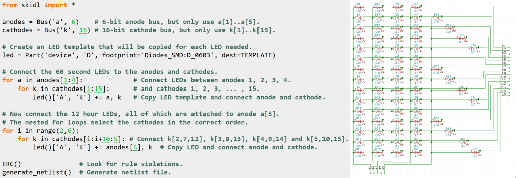
The conference kicked off from a talk by Dave Vandenbout. He gave a humorous history of schematics before telling about a tool that eliminates the need to draw them. He created a Python-based tool called SKIDL. With SKIDL it is possible to describe a schematic entirely as a Python script. It outputs a netlist that is usable in KiCad’s PCB editor
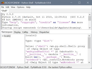
Dave’s tool is not the only place that Python showed up at KiCon 2019. It seemed that every talk on automating something in KiCad had Python at its core. Something else I learned is that pcbnew has a Python shell built-in to it. From what Wayne says, it sounds like with version 6 the Schematic editor will get one too.
2. It is time to Learn Git
Mike Ossmann founded Great Scott Gadgets. They sell tools for hacking RF signals. During the KiCon panel with the KiCad developer team, he asked about improvements for using git with PCB files. He was not the only one that brought up issues with git and PCB files. While I haven’t had experience merging multiple people’s PCB’s work together, it sounds like there is a lot of metadata KiCad generates which makes git merges a nightmare. But, it was refreshing to hear the dev team give some suggestions and acknowledge it is an area to improve.
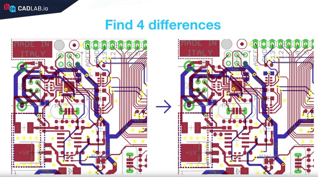
In his talk, Dmitry Zhgenti went through the 10 Git commands you need to know. The primary subject for him was how to do visual comparisons between schematics and PCBs. His company, CADLAB.io, provides a visual diff tool that works with EAGLE and KiCad. With KiCad support added just in time for KiCon! I’m curious how his tool works in practice, so I might be asking for help from you guys to test it out.
3. What atomic library means
Back in late 2017, Digi-Key released their atomic KiCad Library. I did not understand what atomic meant.

During the developer panel discussion, someone asked Wayne if KiCad would move towards an atomic library. He explained what it meant and why he did not feel the need to move KiCad that direction. An atomic library links PCBs footprints to schematic symbols. If you have not used KiCad before, its default libraries do not make such a linkage. When capturing a schematic, you must select a footprint to go with the schematic symbol.
The open source library that Digi-Key provides includes a footprint in the metadata for library symbols. In their case, this decision makes sense. Their goal is to provide a library of components that are orderable (from Digikey, of course.) I do not think there is a “better” answer to atomic vs. whatever-the-opposite-is-called. What I do like is that KiCad offers the flexibility to support both effectively.
4. FreeCAD is a “real” CAD program
When it comes to mechanical CAD work, Fusion 360 is my go-to tool today. Years ago I learned how to use Inventor. Early F360 worked as Inventor did, so the transition was simple. The ultimate integration of eCAD and mCAD is exporting a 3D model of a PCB with components, import into mCAD, move a connector, and export back to eCAD. EAGLE 9 flirts with this idea, but its workflow is less than ideal.
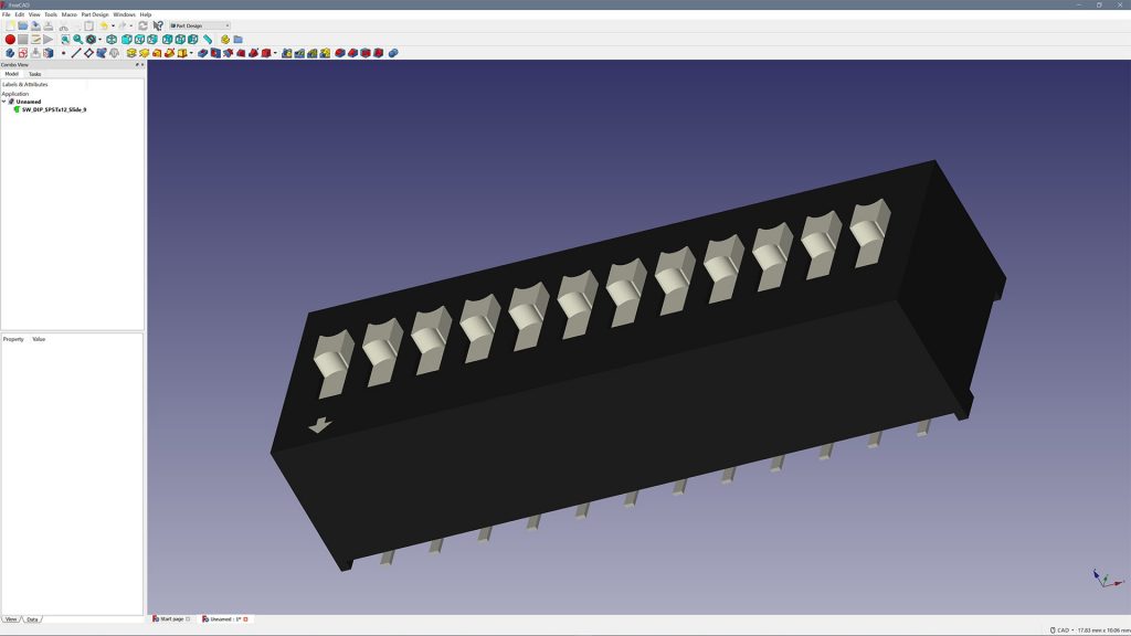
Anool ran a KiCon Workshop on 3D modeling using FreeCAD. I did not realize the 3D component models included with KiCad were created with FreeCAD. I did not know FreeCAD was a functional parametric CAD program at all! In the past, I only used it to convert STEP files from Fusion 360 into WRL (VRML) to use in KiCad’s 3D exporter!
I do not have much to say about FreeCAD today, but it is something I plan to give a closer look soon. If for no other reason, than it is much lighter weight than Fusion 360. (And appears to work better when offline.)
5. The KiCad project needs more than code
My second favorite thing about the conference was to meet and hear directly from the lead developers. When Seth Hillbrand talked about laying out RF traces, he said “that is why I am working on that” a few times. It took me an embarrassing amount of time to realize he meant; he is writing the code that is going into KiCad. (As someone starting to use KiCad for RF design, I’m glad he’s working on it!)
The talk by Jon Evans laid out a process to move from user to developer, which takes time because the KiCad code base is extensive. However, he also pointed out that there are other areas that KiCad could use help. For example, if you find a bug, providing a gdb tracepoints the right developer in the right direction. Especially compared to a bug report that says “it crashed.”
Another area that always needs help is documentation. Or for those of you who are multi-lingual, translations are still in need of help. Last, several developers mentioned, installers are an issue as well. We all want the glory of adding a cool new feature. However, there are many other elements that many other users can help with that are just as important even if they are not that blinky.
6. Simulation (SPICE) tricks
Everyone, or at least me, had a dream of using KiCad 5 to capture a schematic, layout the PCB, and in between hit the simulate button to see how the circuit functions. KiCad 5 provides an interface a circuit simulator known as ngspice. If you aren’t familiar with it, let’s call it an open source PSPICE program. In other words, it is a circuit simulator.
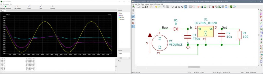
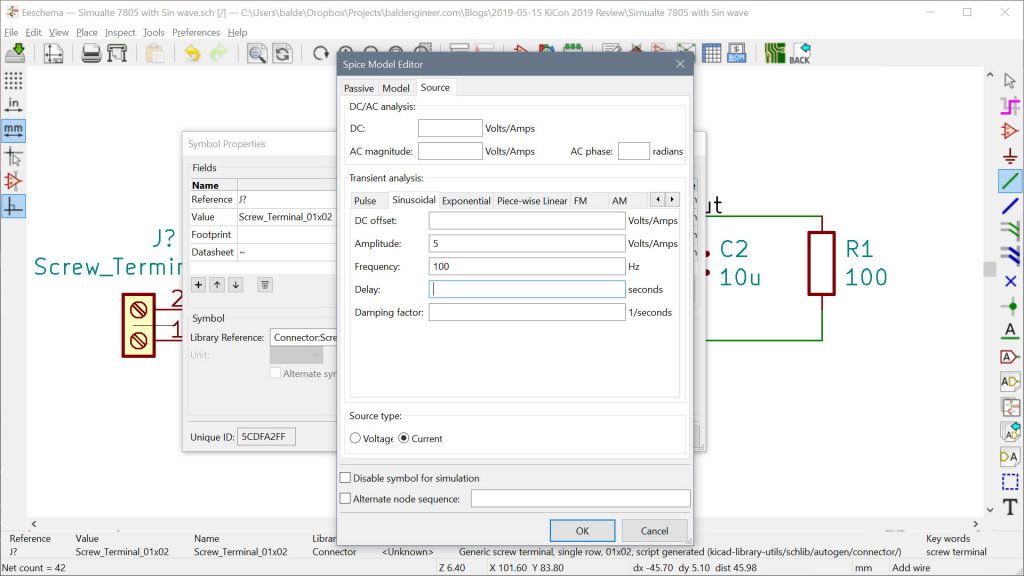
It turns out that, simulation is not as simple as a single button push. You need particular sources, models for active components, and to know some pspice directives. What I learned from Stephan Kulov’s talk is that you do not HAVE to use the specific components in the “pspice” symbol library.
In his demonstration, he added SPICE directives to existing schematic symbols. After all, ngspice does not care what KiCad symbols you use for a device. It only looks at the text-based netlist file for specific information. So for example, if you have a 2-pin header for power, tell ngspice that header is an AC voltage source to make it happy.
There are a few other things you need to do, but at least with Stephan’s talk, I think using KiCad to simulate the same circuit you created a PCB from is perhaps possible.
Conclusion
I also talked at the conference. Mine was on why it is crucial to “Preserve History with Preserve History with KiCad In it, I introduce a project I put together called “Bit Preserve.” Currently, I’m re-capturing PDF-based schematics for 8-bit and 16-bit computers. But, I am going to save that talk and the project for another post.
Overall, KiCon 2019 was a massive success in my eyes. As I said multiple times, bringing together various hardware engineering disciplines to exchange ideas and best practices is fantastic. The range and depth of topics meant there was something for every hardware developer level. For the full list of videos and talks, take a look through the this playlist on the Contextual Electronics YouTube channel. (At the time of this post, they are still being added.)

6 Comments
This was a very useful summary (even though I’m almost a year behind) – just wanted to comment saying thank you and keep it up!
One other thing about Kicad and 3D stuff is that 2 years ago I added the ability to export boards to STEP. I originally added the IDF3 export before that, but IDF was too crude for what I needed so I eventually added STEP export. These days there are 2 schemes for creating a STEP file of the PCB + components; some people prefer to use the ‘KiCad StepUp’ scripts, especially if they also want photo-realistic rendering of the PCB, but KiCad also has a plugin to export directly to STEP and will include all components which have an associated IGES or STEP model. I haven’t been an active developer for about 2 years now, so I have no idea if anyone actually packages that option in prebuilt stuff, but the source is all there.
Thanks! Great Wrap Up!
FreeCAD is useful, indeed, for the purposes outlined above. For general purpose drawing, though, there is a problem in that FreeCAD does not support tolerances. Drawings submitted to a machine shop mean little without tolerances. I had to use LibreCAD for that reason.
Great write-up; I really enjoyed the conference!
Thank you very much for a detailed write up. It felt as if I was attending the conference with you. Good to know about Python and Git integrations.