As a kid, I got the book “Upgrading and Repairing PCs.” (Now in its 22nd edition.) It was the first book to explain to me the PC architecture. I considered, how were there so few pins on an AT-style keyboard connector when there were 101 keys on the keyboard? That is when I first learned about the keyboard matrix.
Original image from Deskthority Wiki. (Edited image is shown.)
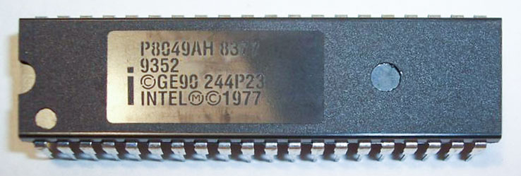
The keyboard matrix itself did not amaze me, but instead the idea there was an entirely separate 8-bit microcontroller inside of the keyboard. Early keyboards may have used the P8049AH, which, there is still some stock available to purchase. I was fascinated with the idea an entire computer was necessary to run the keyboard, to use my “real” computer. Why did it take something as complicated as a microcontroller?
The key benefit (get it?) of a keyboard matrix is that it reduces the number of pins necessary to capture the input of a large number of the keys. Even though a PC keyboard has 101 keys, it does not mean there is a microcontroller with 101 pins. Nor does it need a cable with over 100 wires.
I will first explain with simple four and nine button examples.
Without a matrix
First, let’s look at what happens with four buttons. Without an array, each switch would get an input pin. This count probably does not sound bad. Now, what if you used nine buttons instead of just 4?
You would need 9 I/O pins! Also, consider the cost of wiring that many individual buttons. If the buttons are on a different PCB from the microcontroller or you are hand wiring a prototype, that is many wires.
Let’s put those same nine buttons into a 3×3 matrix. This method saves you three pins!
Elements of a Keyboard Matrix
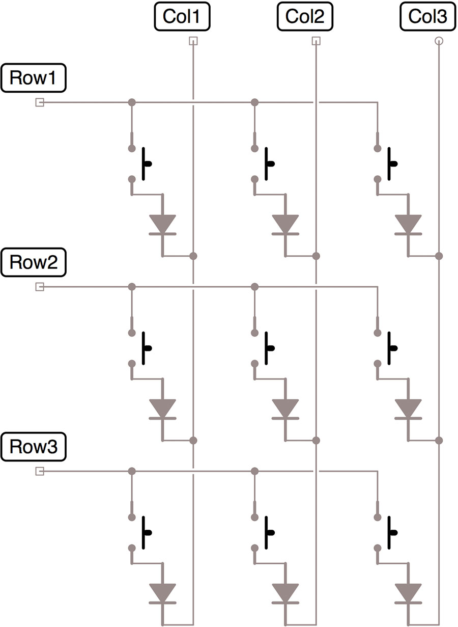
Every matrix has rows and columns. By accessing a single row and a single column, we can individually access each button. This method drives one side and senses the other.
Keyboard Matrix Diodes
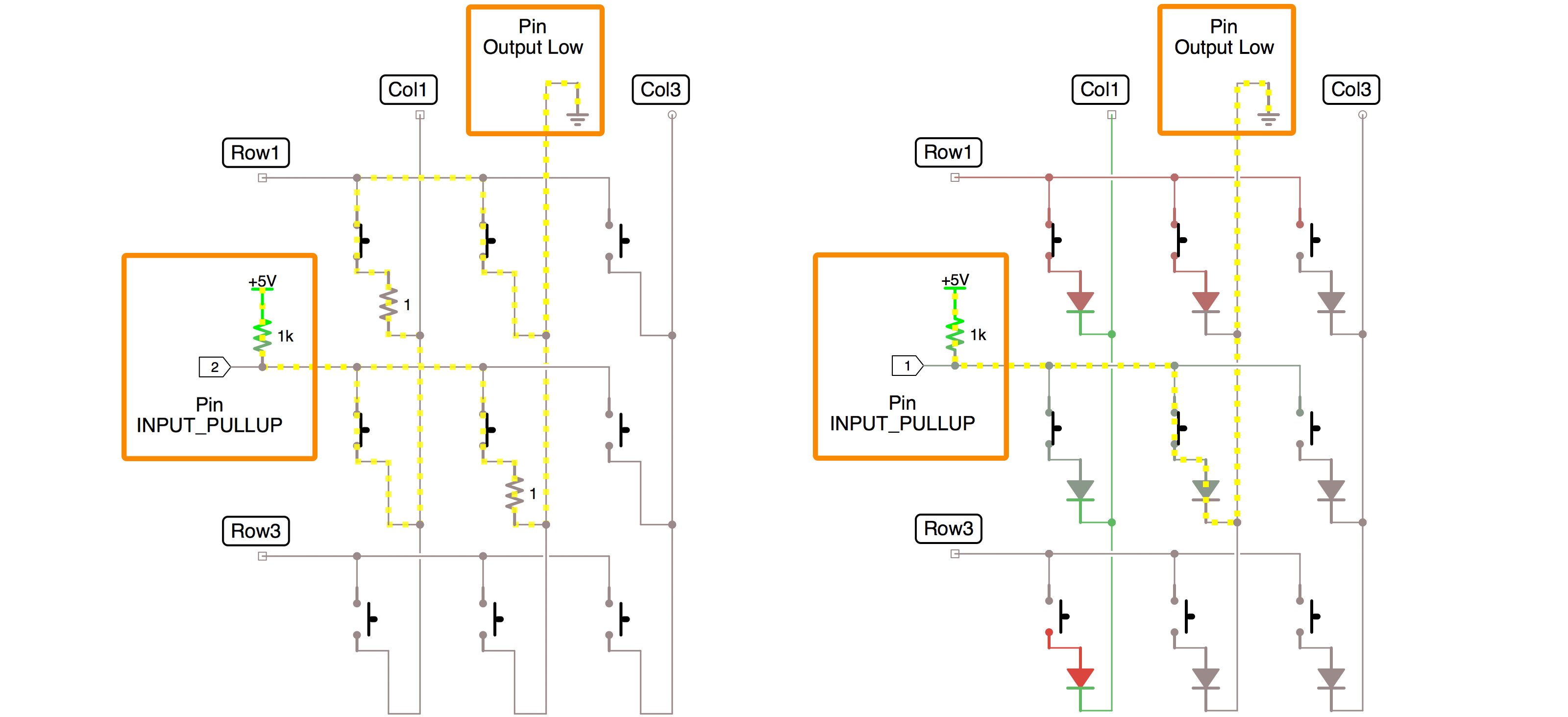
Matrix with and without blocking diodes
In the schematic, I have included blocking diodes. The diode prevents a condition called “ghosting.” In a keyboard matrix, ghosting means you see non-existent button pushes.
The image above compares the same button presses with and without diodes. (The 1 ohm resistors keep iCircuit from getting annoyed with short circuits.) On the right-side schematic, reading the “selected” button happens with no additional current paths.
Keyboard Matrix Code
For() loops and arrays make the code work. The steps for scanning the keyboard matrix include:
Enable the column
Scanning each row
Capture button state
Disable the column
// Keyboard Matrix Tutorial Example
// baldengineer.com
// CC BY-SA 4.0

// JP1 is an input
byte rows[] = {2,3,4};
const int rowCount = sizeof(rows)/sizeof(rows[0]);

// JP2 and JP3 are outputs
byte cols[] = {8,9,10};
const int colCount = sizeof(cols)/sizeof(cols[0]);

byte keys[colCount][rowCount];

void setup() {
	Serial.begin(115200);

	for(int x=0; x<rowCount; x++) {
		Serial.print(rows[x]); Serial.println(" as input");
		pinMode(rows[x], INPUT);
	}

	for (int x=0; x<colCount; x++) {
		Serial.print(cols[x]); Serial.println(" as input-pullup");
		pinMode(cols[x], INPUT_PULLUP);
	}

}

void readMatrix() {
	// iterate the columns
	for (int colIndex=0; colIndex < colCount; colIndex++) {
		// col: set to output to low
		byte curCol = cols[colIndex];
		pinMode(curCol, OUTPUT);
		digitalWrite(curCol, LOW);

		// row: interate through the rows
		for (int rowIndex=0; rowIndex < rowCount; rowIndex++) {
			byte rowCol = rows[rowIndex];
			pinMode(rowCol, INPUT_PULLUP);
			keys[colIndex][rowIndex] = digitalRead(rowCol);
			pinMode(rowCol, INPUT);
		}
		// disable the column
		pinMode(curCol, INPUT);
	}
}

void printMatrix() {
	for (int rowIndex=0; rowIndex < rowCount; rowIndex++) {
		if (rowIndex < 10)
			Serial.print(F("0"));
		Serial.print(rowIndex); Serial.print(F(": "));

		for (int colIndex=0; colIndex < colCount; colIndex++) {
			Serial.print(keys[colIndex][rowIndex]);
			if (colIndex < colCount)
				Serial.print(F(", "));
		}
		Serial.println("");
	}
	Serial.println("");
}

void loop() {
	readMatrix();
	if (Serial.read()=='!')
		printMatrix();
}
1. Column Enable (Line 32)
Keyboard matrix columns are enabled by setting the pin to OUTPUT and then to LOW. This step provides the path to ground. The rest of the columns pins are held in their high impedance state, effectively disabling them from the matrix.
2. Scan each row (Line 39)
A for() loop runs through each pin the row array. The pin’s input pull-up resistor is enabled, providing the connection to VCC. Most Arduino boards turn on the resistor with pinMode()’s INPUT_PULLUP state.
3. Capture the pin’s state
A two-dimensional array stores the pin’s value. The pin’s pull-up resistor is turned off, and the loop increments.
The idea here is to capture all of the pressed buttons. After the matrix has been scanned action can be taken. Just like with regular buttons, you could also create a “previous state” matrix to detect button state changes.
Once read, the pin’s state goes back to INPUT, disabling the row by turning off the pull-up resistor.
Bitwise operators would be better
I’d like to point out; this method is very memory inefficient. The problem is that an entire byte, or 8 bits, is being used to store the state of each button. You only need 1 bit for each. A more efficient method would be using bitwise operators to keep track of each key as a bit.
4. Disable the Column
After checking each row, putting the column pin back to an INPUT state disables it.
Processing the newly acquired button presses happens after scanning the entire matrix. In this example code, the function “printMatrix()” prints the contents of the array. In your sketch, you would perform some action based on the button’s states.
Potential Optimizations
As mentioned before, you could be using bit operators to store each button press as a single bit, instead of a byte.
Converting the code into a state machine using millis() could be critical on slower MCUs or very time sensitive code. As it is, most matrices will be scanned so fast the blocking time doesn’t matter. However, I could imagine using a microcontroller at 1 MHz where the time it takes for a large matrix read to finish might be too much.
Alternative code
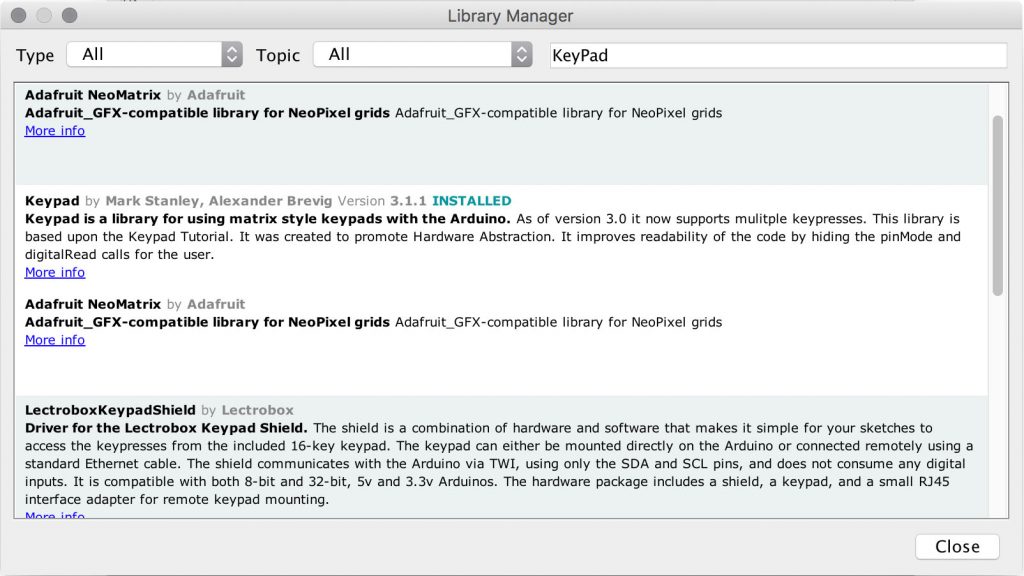
There is an Arduino keyboard matrix library available. You can install Keypad from the Library manager.
It simplifies programming a matrix. The most effort is defining the keys. A trade-off with the stock library is that it does not handle multiple key presses. There’s a code example for that, but that adds to the complexity.
Conclusion
A keyboard matrix is a great way to add buttons without using up all of your I/O pins. In this keyboard matrix tutorial, I showed how a 9-button matrix works. This same code and circuit are what I’m using for a new project. My latest project has 64 buttons. More on that to follow.
Fan of making things beep, blink and fly. Created AddOhms. Writer for Hackster.io News. Freelance electronics content creator for hire! KN6FGY and, of course, bald.
I don’t know if this is still monitored but I have a question about the matrix, which is an “active low” one if I’m not mistaken.
Sparkfun, when explaining the same kind of matrix, has the diodes’ anode/catode reversed, and I’m wondering who’s wrong or why.
I assume that the upper button in the middle column should be considered to be open. Otherwise row 1 would be active in both figures and reporting (1,2) as active would be correct. This might also solve your problem with iCircuit.
Thanks for this – made it easy to trace how a single button push flows.
Still have one question, as to how to detect multiple buttons being pushed.
If I number the 3×3 buttons as:
123
456
789
How do I know if it is 1, 2 and 4 being pushed, versus 1, 2 and 5? Wouldn’t either combination trigger col1 and col2, and row1 and row2?
Thanks.
I have no idea if you’ll reply, but I’m trying to convert an old pipe organ console to MIDI. Long story short, I need to use multiplexers and create a matrix for the keyboard, but I’m unsure what sort of multiplexers I need, or how many. I want to achieve 16+ note polyphony, across a 61 note keyboard.
Not an expert on electronic musical keyboards, couldn’t this approach (matrix + multiplexing) be potentially incompatible with the time responsiveness required in music or potentially limit the polyphony your keyboard could transmit?
Using the attached library I was able to use an Arduino mega to midify a 2 manual organ with a full pedal board and 30+ stops. I’m currently working on building a 3rd manual and adding illuminated LED push buttons to replace the stops. The Arduino plugs into the computer and can be programmed to show up as a midi device. https://tttapa.github.io/Control-Surface-doc/Doxygen/index.html
Hello,
I tried that with 5×5 and the code … SoMeHoW work…
When I push middle button output is
11111
11111
00100
11111
11111
Is there something with inversion?
Or am I missing something?
Thanks for the code and the logic. I picked up some used 4X4 keypads at a sale (8 pinout) and with a vom figured the columns and rows and ground. Using the matrix library functions
worked fine on my uno, but did not work on my mini or nano arduinos. Do you know if
there is a special library for those versions? Also, can you recommend any ic that would simplify interfacing the keypad to the arduino without the pin overhead that the above methods use? I am thinking a SN74151 (1 of 8 data selector … I have crates of em’) would cut the IO pins to four, but the logic to make it work would be pretty sticky.
Not sure what you mean by a mini, but a Nano is the same 328p as the Uno. So there must be a wiring issue, because there is no difference in the code. It is the same processor silicon.
can you recommend any ic that would simplify interfacing the keypad to the arduino without the pin overhead that the above methods use? I am thinking a SN74151
On something small like a 4×4, I don’t see how a multiplexer and shift register is going to help. You burn up as many pins to control those chips as you would to control the matrix directly.
Is it possible to have two separate button matrixes. I have two 28 buttons in a 4×7 grid for a multiaxis joystick and gamepad using a joystick library by Matthew Heironimus
Like other websites, this one uses cookies to remember things. Mostly, I use Google Analytics to know how many people come here. ¯\_(ツ)_/¯
By clicking “Accept”, you consent to the use of ALL the cookies.
This website uses cookies to improve your experience while you navigate through the website. Out of these, the cookies that are categorized as necessary are stored on your browser as they are essential for the working of basic functionalities of the website. We also use third-party cookies that help us analyze and understand how you use this website. These cookies will be stored in your browser only with your consent. You also have the option to opt-out of these cookies. But opting out of some of these cookies may affect your browsing experience.
Necessary cookies are absolutely essential for the website to function properly. These cookies ensure basic functionalities and security features of the website, anonymously.
Cookie
Duration
Description
cookielawinfo-checkbox-advertisement
1 year
Set by the GDPR Cookie Consent plugin, this cookie is used to record the user consent for the cookies in the "Advertisement" category .
cookielawinfo-checkbox-analytics
11 months
This cookie is set by GDPR Cookie Consent plugin. The cookie is used to store the user consent for the cookies in the category "Analytics".
cookielawinfo-checkbox-functional
11 months
The cookie is set by GDPR cookie consent to record the user consent for the cookies in the category "Functional".
cookielawinfo-checkbox-necessary
11 months
This cookie is set by GDPR Cookie Consent plugin. The cookies is used to store the user consent for the cookies in the category "Necessary".
cookielawinfo-checkbox-others
11 months
This cookie is set by GDPR Cookie Consent plugin. The cookie is used to store the user consent for the cookies in the category "Other.
cookielawinfo-checkbox-performance
11 months
This cookie is set by GDPR Cookie Consent plugin. The cookie is used to store the user consent for the cookies in the category "Performance".
CookieLawInfoConsent
1 year
Records the default button state of the corresponding category & the status of CCPA. It works only in coordination with the primary cookie.
viewed_cookie_policy
11 months
The cookie is set by the GDPR Cookie Consent plugin and is used to store whether or not user has consented to the use of cookies. It does not store any personal data.
Functional cookies help to perform certain functionalities like sharing the content of the website on social media platforms, collect feedbacks, and other third-party features.
Cookie
Duration
Description
language
session
This cookie is used to store the language preference of the user.
Performance cookies are used to understand and analyze the key performance indexes of the website which helps in delivering a better user experience for the visitors.
Analytical cookies are used to understand how visitors interact with the website. These cookies help provide information on metrics the number of visitors, bounce rate, traffic source, etc.
Cookie
Duration
Description
_ga
2 years
The _ga cookie, installed by Google Analytics, calculates visitor, session and campaign data and also keeps track of site usage for the site's analytics report. The cookie stores information anonymously and assigns a randomly generated number to recognize unique visitors.
_ga_LHR6J24XSY
2 years
This cookie is installed by Google Analytics.
_gat_gtag_UA_42726312_1
1 minute
Set by Google to distinguish users.
_gid
1 day
Installed by Google Analytics, _gid cookie stores information on how visitors use a website, while also creating an analytics report of the website's performance. Some of the data that are collected include the number of visitors, their source, and the pages they visit anonymously.
browser_id
5 years
This cookie is used for identifying the visitor browser on re-visit to the website.
CONSENT
2 years
YouTube sets this cookie via embedded youtube-videos and registers anonymous statistical data.
Advertisement cookies are used to provide visitors with relevant ads and marketing campaigns. These cookies track visitors across websites and collect information to provide customized ads.
Cookie
Duration
Description
VISITOR_INFO1_LIVE
5 months 27 days
A cookie set by YouTube to measure bandwidth that determines whether the user gets the new or old player interface.
YSC
session
YSC cookie is set by Youtube and is used to track the views of embedded videos on Youtube pages.
yt-remote-connected-devices
never
YouTube sets this cookie to store the video preferences of the user using embedded YouTube video.
yt-remote-device-id
never
YouTube sets this cookie to store the video preferences of the user using embedded YouTube video.
yt.innertube::nextId
never
This cookie, set by YouTube, registers a unique ID to store data on what videos from YouTube the user has seen.
yt.innertube::requests
never
This cookie, set by YouTube, registers a unique ID to store data on what videos from YouTube the user has seen.

 You would need 9 I/O pins! Also, consider the cost of wiring that many individual buttons. If the buttons are on a different PCB from the microcontroller or you are hand wiring a prototype, that is many wires.
Let’s put those same nine buttons into a 3×3 matrix. This method saves you three pins!
You would need 9 I/O pins! Also, consider the cost of wiring that many individual buttons. If the buttons are on a different PCB from the microcontroller or you are hand wiring a prototype, that is many wires.
Let’s put those same nine buttons into a 3×3 matrix. This method saves you three pins!
 It simplifies programming a matrix. The most effort is defining the keys. A trade-off with the stock library is that it does not handle multiple key presses. There’s a code example for that, but that adds to the complexity.


16 Comments
This is the guide I was looking for to understand how the keyboard matrix works. Thanks ;))
I don’t know if this is still monitored but I have a question about the matrix, which is an “active low” one if I’m not mistaken.
Sparkfun, when explaining the same kind of matrix, has the diodes’ anode/catode reversed, and I’m wondering who’s wrong or why.
https://learn.sparkfun.com/tutorials/button-pad-hookup-guide/background
Could someone please comment on this?
Pingback: Keyboard Switch Report – phil caridi
I assume that the upper button in the middle column should be considered to be open. Otherwise row 1 would be active in both figures and reporting (1,2) as active would be correct. This might also solve your problem with iCircuit.
Thanks for this – made it easy to trace how a single button push flows.
Still have one question, as to how to detect multiple buttons being pushed.
If I number the 3×3 buttons as:
123
456
789
How do I know if it is 1, 2 and 4 being pushed, versus 1, 2 and 5? Wouldn’t either combination trigger col1 and col2, and row1 and row2?
Thanks.
The issue you are describing is “ghosting.” That’s why the diodes are needed.
I have no idea if you’ll reply, but I’m trying to convert an old pipe organ console to MIDI. Long story short, I need to use multiplexers and create a matrix for the keyboard, but I’m unsure what sort of multiplexers I need, or how many. I want to achieve 16+ note polyphony, across a 61 note keyboard.
Sorry, not an area I have a lot of experience. You might try posting on something like the Arduino.cc Project Guidendance forum.
Not an expert on electronic musical keyboards, couldn’t this approach (matrix + multiplexing) be potentially incompatible with the time responsiveness required in music or potentially limit the polyphony your keyboard could transmit?
Using the attached library I was able to use an Arduino mega to midify a 2 manual organ with a full pedal board and 30+ stops. I’m currently working on building a 3rd manual and adding illuminated LED push buttons to replace the stops. The Arduino plugs into the computer and can be programmed to show up as a midi device.
https://tttapa.github.io/Control-Surface-doc/Doxygen/index.html
Hello,
I tried that with 5×5 and the code … SoMeHoW work…
When I push middle button output is
11111
11111
00100
11111
11111
Is there something with inversion?
Or am I missing something?
The code should work fine for a 5×5, if modified correctly. The pattern suggests to me you did not wire it the same.
Thanks for the code and the logic. I picked up some used 4X4 keypads at a sale (8 pinout) and with a vom figured the columns and rows and ground. Using the matrix library functions
worked fine on my uno, but did not work on my mini or nano arduinos. Do you know if
there is a special library for those versions? Also, can you recommend any ic that would simplify interfacing the keypad to the arduino without the pin overhead that the above methods use? I am thinking a SN74151 (1 of 8 data selector … I have crates of em’) would cut the IO pins to four, but the logic to make it work would be pretty sticky.
Not sure what you mean by a mini, but a Nano is the same 328p as the Uno. So there must be a wiring issue, because there is no difference in the code. It is the same processor silicon.
On something small like a 4×4, I don’t see how a multiplexer and shift register is going to help. You burn up as many pins to control those chips as you would to control the matrix directly.
Is it possible to have two separate button matrixes. I have two 28 buttons in a 4×7 grid for a multiaxis joystick and gamepad using a joystick library by Matthew Heironimus
I have never used that library, so I cannot say.