
Out of context screenshots are out of context
On the Mini Apple IIe project, I am testing the composite/sync amplifier, which is an MC1377. The composite output looks great, until connecting the output cable to a receiver. It outputs about 2.6 Vpp until loaded with 75 ohms, then it drops to about 400 mVpp. We have replaced most of the passives on the output and have tried 3 different MC1377s. The measurements below are from a known good MC1377 removed from a working Apple IIgs.
Here is an MC1377 datasheet mirror link. The Figure references below match Page 8 of that datasheet. The biggest suspects are the Luma signals.
Not captured, but tested, none of the input signals change amplitude when the output (pin 9) is loaded with a 75 ohm load.
Problem: Update, SOLVED
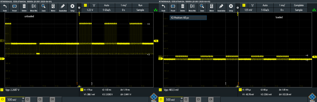
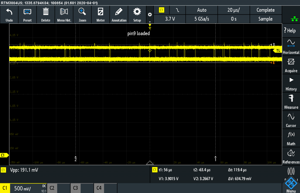
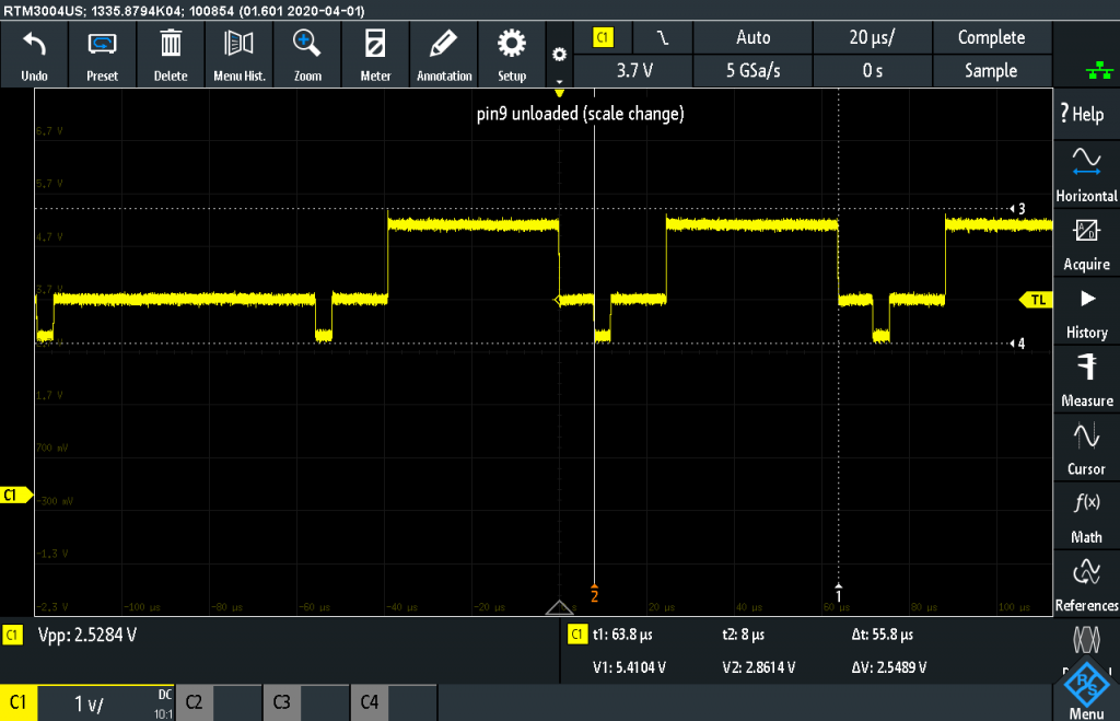
These two screenshots are the same point, RCA Out Header in the schematic. On the left is the output when the node is left open. It is about 2.6Vpp with minimal DC offset. However, when the signal is terminated with a 75 ohm resistor (or a receiver circuit) it drops to about 300 mVpp!
Circuit
The circuit is a copy of the circuit from the Apple IIgs. In that circuit, there was a “capacitive transformer” which appears to be an EMI filter. That part was omitted in the VGC protoboard. In case it did some kind of isolation, we removed the same component from a working Apple IIgs, but it did not have an appreciable effect.
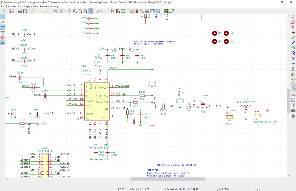
Full VGC Protoboard KiCad files are available here.
Screenshots from VGC Protoboard rev1
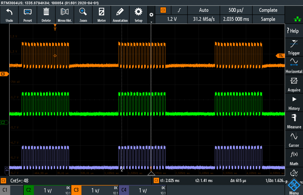
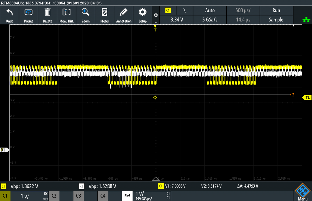
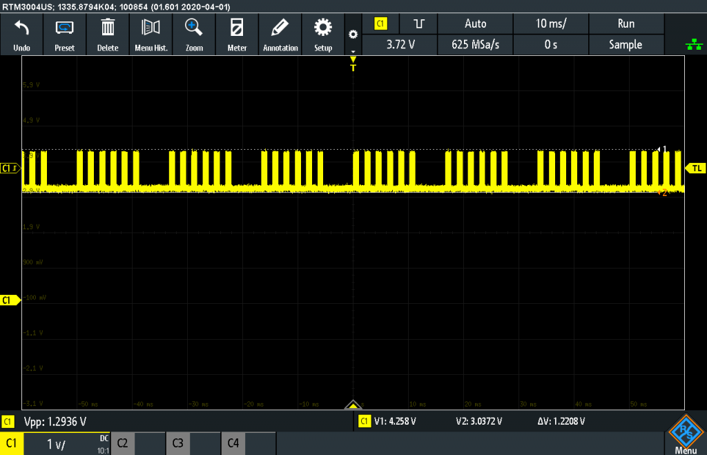
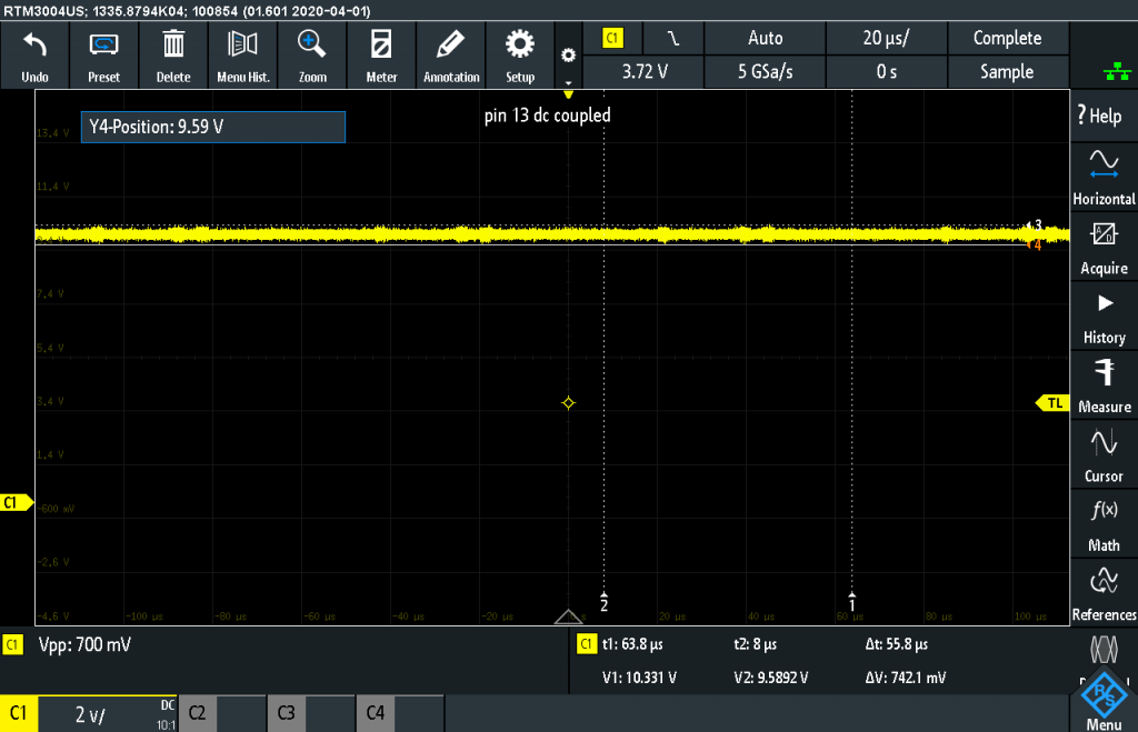

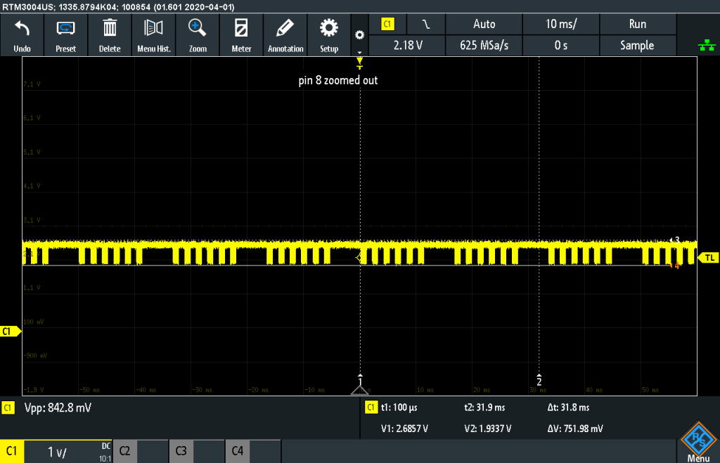
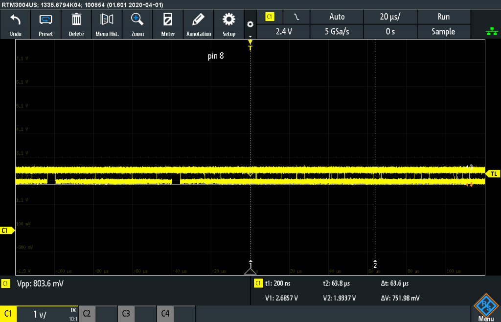
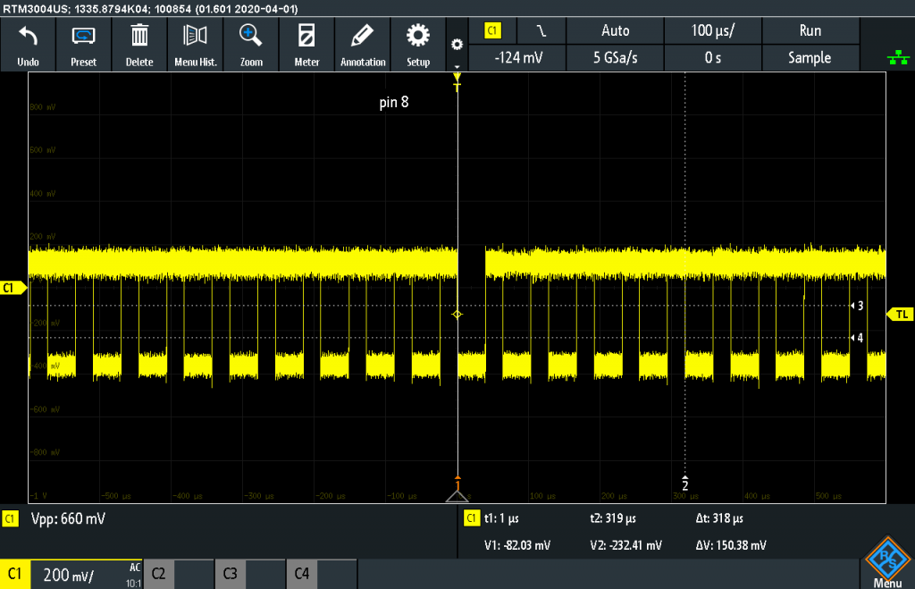
15- Luma In AC Coupled, showing activity

