Abstract
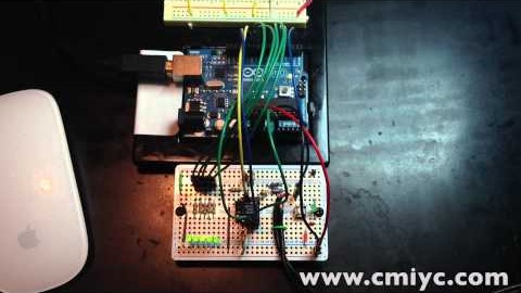
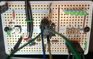
Mixed Signal Integration has a cool little chip that has 7 built-in bandpass filters. Run an audio signal through it and you have an instant audio spectrum analyzer! This is a simple spectrum analyzer based on an Arduino. Each of the 5 LEDs represent a single section of the chip’s 7 sections of audio spectrum.
Electronics
If you want to replicate this setup, here is the hardware you’ll need to get.
Parts list:
- (1) – MSGEQ7 (Sparkfun)
- (5) – LEDs
- (5) – 470Ω Resistors
- (1) – 180kΩ Resistor
- (1) – 22kΩ Resistor
- (1) – 33pF Capacitor (Ceramic)
- (1) – 0.01µF Capacitor (Ceramic)
- (2) – 0.1µF Capacitors (Ceramic)
- (1) – Pushbutton
- (1) – Stripped Audio Cable
- Header Pins
- Jumper Wires
- Adafruit Perma-Prototype Board (or Breadboard)
Schematic:
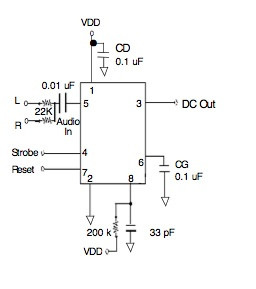
The application example from the MSGEQ7 Datasheet provides the circuit necessary. The 200k and 33pF are probably the most critical components. 200k is not a E24-value, so I used 180K. The 33pF shouldn’t be an issue to find. 470 ohms were picked to keep the amount of current flowing through the Arduino I/O pins low.
Firmware
Since there are only 5 LEDs, I decided to make each frequency band adjust the brightness via PWM. The more energy at each particular band will result in brighter LEDs. The code was compiled in Eclipse with Arduino-0023 Core on an Uno with an ATmega328.
Code is also available from Pastebin: MSGEQ7 Simple Spectrum Analyzer
#define msg7RESET 11
#define msg7Strobe 12
#define msg7DCout 0
const int LEDpins[7] = {3,5,5,6,9,9,10}; // there are 5 LEDs and 7 freq bands. So, repeat LEDs

#define pushButton 2

void setup() {
   // initialize the digital pin as an output.
   // Pin 13 has an LED connected on most Arduino boards:
   for (int x=0; x<7; x++) {
      pinMode(LEDpins[x], OUTPUT);
   }
   pinMode(msg7RESET, OUTPUT);
   pinMode(msg7Strobe, OUTPUT);

   pinMode(pushButton, INPUT); // never actually used in this example.
   digitalWrite(pushButton, HIGH); // Enable internal pull-up
}

void loop() {
   digitalWrite(msg7RESET, HIGH); // reset the MSGEQ7's counter
   delay(5);
   digitalWrite(msg7RESET, LOW);

   for (int x = 0; x < 7; x++){
      digitalWrite(msg7Strobe, LOW); // output each DC value for each freq band
      delayMicroseconds(35); // to allow the output to settle
      int spectrumRead = analogRead(msg7DCout);

      int PWMvalue = map(spectrumRead, 0, 1024, 0, 255); // scale analogRead's value to Write's 255 max
      if (PWMvalue < 50)
         PWMvalue = PWMvalue / 2; // bit of a noise filter, so the LEDs turn off at low levels

      analogWrite(LEDpins[x], PWMvalue);
      digitalWrite(msg7Strobe, HIGH);
   }
}
Demonstration
YouTube Video showing the light’s action along with some music. The music was created using GarageBand’s magic instruments. I liked the groove and how well the lights responded to it. Enjoy!
Project by AntiPuppet:


72 Comments
What I don’t understand: If you are already using an ATMega microcontroller at a high clock frequency, why not ditch the external IC and do the signal processing on the microcontroller? I mean the ATMega controllers are very fast thanks to their hardware multipliers.
Extremely simple and VERY obvious explanation: not everyone knows or wants to do it your way. Some people want to buy a chip that does it with a few lines of code.
Hi, James. Are you there?. I am trying to make one. But it is not working. Can you help me.? The light is not glowing?. I got the chip from sparkfun.
I wrote this eight years ago. I haven’t used it since then. Why not contact Sparkfun for help?
“200k is not a E24-value, so I used 180K.”
But 100K is — and two in series = 200K.
Hi,
Thank tou for the great post.
I’m using a very simliar script to read audio from the same chip but the problem is that every time I turn the system onthe frequencies are not always in the same array index, sometimes the lowest bass is on spectrumValue[5] sometimes in spectrumValue[3] and so on so i can’t get it to look right.
Any toughts?
Sounds like a problem with your code. Maybe the array isn’t indexed correctly.
Hi James, looking to use something similar in a project I’m doing, would this code be easily adapted to create a spectrum analyser that is more of a 5 x 5 LED configuration rather than the 5 single LEDs. Looking to hook this up to my other ongoing project that is a MIDI controller for reaper which will be used to control the EQ in reaper and then use this spectrum analyser as a display. Do you think this is possible, which i presume it is, and the ease of this project?
Also, i currently have 7 different colour LEDs, so i pressure i could use the chip to its full capacity and split into 7 bands too?
1 LED per band is relatively easy. To have multiple lights per band would take a bit of effort. Either each LED would need its own I/O pin or you would need shift registers. Then you run into issues with how to power that many LEDs at once. Even with a 2560 AVR board, which has plenty of I/O pins, you could only turn on 20 or so LEDs at once. (AVRs are limited to something like 200mA total.) Shift registers add a bit of delay which can be an issue since there is already a slight delay getting the reading from the MSGEQ7.
So is it possible? Yes. Is it going to be the best spectrum analyzer? No.
If I were approaching this project, I would use a shift register on each band. And hope it is fast enough.
Thanks, i have seen some examples online of DIY LED Matrix, where the pins of the LEDs are overlapped, just wondering if you’ve ever come across this and whether that would be able to be incorporated into your idea…
Yeah. (duh.) My bad. Matrix is another way. I was stuck on isolating the bands.
Cant seem to get my head around how i would implement this into an LED matrix, should it work the same way, or will i have to send the data of the 7 frequency bands from the chip to the leds in a different way, the more research i do the more conflicting argument i seem to read. My extent of arduino up to this point goes as far as simple DMX and MIDI controllers, so some of posts i read in forums can go straight over my head, but I’m really wanting to do this project even if the spectrum analyser turns out to just be a fun added graphic as it won’t be the most accurate, but i feel like completing this project will help my understanding and ability of using arduino.
How could this code be modified to trigger relays to turn on and off christmas lights? I like the simplicity of the code and I dont need anything fancy.
Determine an “on” and “off” value of the analogRead, for each band. If the value is lower, use digitalWrite() to turn the replay off. If higher, turn it on. You’ll need a driver, like a transistor,to drive the relay. Also, relays are SSSLLLOOOWWWW, but you find that out when you do some testing.
Thanks! What would be an alternative for use with incandescent bulbs? I’m trying to create a vintage style color organ with modern safer components, but love the look of the halogen bulbs as opposed to LED’s. Any tips?
I don’t know what you mean by “alternative.” Relays are relays. There are solid state relays, which are like transistor switches for AC. And there are electromechanical relays, which are slow.
Just a note on bad chips – I bought 10 MSGEQ7s on ebay. The first two I used were fine so I assumed I had a good batch. But having spent hours wondering what was wrong on the next project I then swapped a few around and discovered that only 4 out of the 10 worked. The others ranged from nothing at all to random flickering.
Hi Sir,
I do my project atmega 32a microcontroller at atmel studio but i want sound frequency meter circuit and coding. because this is in ardino how to convert ateml?
please, help me!
I will also want circuit diagram of the sound frequency meter
i cant mister senthur
Hi James,
I have the same question as 1 guy before me, which you didn’t respond to. I built the same circuit as you did, but i hooked a rgb led strip to it (red green and blue with 1 mosfet each). The led strip is running at 12V, so I decided to take an Arduino Nano which can handle this voltage. The problem i have is: when i use the 12V power supply for the leds and the arduino, i get a very strange noise (every color is blinking at about the same frequency). This, however, doesn’t happen when i use the normal usb cable of the arduino. Any Ideas?
Thanks =)
I had this problem with cheap LedPower supplies. They are outputting noise while the PC is powered via a proper ATX PSU. Just buy a better Led PSU or use an ATX PC PSU.
Can provide a schematic or drawing of how you’re hooked up and what the 12V supply is?
Sorry for not responding so fast, but I killed my MSGEQ7 and my Arduino =/ I’ll tell you as soon as I get new parts!
Hi James,
Thanks for your wonderful write-up. This has been instrumental for helping me figure out this chip. I’m using the arduino outputs to switch 7 LED strips through a Darlington Transistor. It all seems to be working fine, but I have one issue. Three of the channels are constantly on, even when I grounded the input. I’m splitting off the audio signal from an audio signal. I believe it’s the 160Hz, 1kHz, and 2.5kHz channels that are always on. The color will change with the audio signal, but it does not have as high of a range (since there is a constant DC background). Have you experienced anything like this? Thanks so much for your help!
If grounding the input doesn’t cause the channels to go back to (or near) 0, then it suggests there’s a problem with the chip.
Inside of the chip are a bunch of filter networks. It is possible they were damaged. Have you been able to try a different chip?
Hi, I have collected , but does not work. LEDs are simply shone . Sometimes it does not shine . What could it be ? thank you
Bad chip.
Looks like a cool little project that is explained very well. I would like to try this but with an electret microphone, rather than audio in. I’m very new to micro electronics so just wanted to ask if this would make any difference. i.e. would the 22K resister still be needed before the 0.01uf capacitor? Thanks in advance.
You will need to use some kind of amplifier with the microphone. A simple op amp based amplifier will work.
I would keep the resistors in. They help protect the inputs of the MSGEQ7.
Cheers James. I now just need to find a good IC distributed in AUS and get busy. Will let you know how it goes. 🙂
Awesome. Please, keep me updated. Maybe I can add a video of your project when you get it working! 😉
Just getting 1’s and 2’s on the serial monitor (meaning no input at all, right?). I’m winding how easy it is to blow the chip, I may have wired it incorrectly at first. Or it just might be a bad chip from eBay. Can I apply a test voltage somewhere to troubleshoot?
Personally, I would spend very little time debugging a part from eBay. They are often b-runs, counterfeits, or parts that didn’t pass test. Not worth saving a few dollars in my opinion.
That said, it is relatively easily to blow the inputs.
Thanks a lot for the help. I’ll order another chip from a more reputable source and be sure to get the wiring right the first time.
I got the spectrum analyzer working, and I want to have the data from it control an LED RGB individually addressable strip light. But, when I plug in the LED strip lights, they create “noise” that causes inaccurate readings on the spectrum analyzer (not sure if the mic or the spectrum analyzer are picking up the noise). If I switch the LED strip lights to a different power supply, it clears up. But, ideally I’d like to power the LEDs off the same power supply, coming from the arduino, too. Any ideas how to clean up the power to filter out the noise from the LEDs?
Thanks for a great instructional!
Hi there, I got your code via Liz Clark’s blog and built the kit in the video by mounting the LEDs in acrylic / plexiglass blocks. Am pleased with the result. Kind regards Robert
https://www.youtube.com/watch?v=yinBXoREQug
Thanks for sharing. It looks pretty awesome!
Hi,
I have a problem with the msgeq7, that i get minimal peaks at the first reading if i use reset and all 7 frequencys. full description here: http://forum.arduino.cc/index.php?topic=217362.0
Its very complicated. all i need is your help, to just run my program (correct pins maybe), play some music and post the whole serial output after one minute (it might be very long, use pastebin). so i can see if my chip is broken or the chip in general has some issues. please also post your wiring, cause everyone is using a different wiring. and if you know where you bought it, it would be also nice to know where. This is my wiring (pic is not mine, and I have a 22k resistor between condenser and audio in)
http://nuewire.com/wp-content/uploads/2011/07/schem1-450×600.png
download programm (you dont need to understand, just change pins maybe and start)
https://mega.co.nz/#!CFpwxTjK!Qwqflh_gNaLdow1pivCvMxDUeCoSjkJcniKpobPMwHc
message me via [email protected] so I am notified that you posted something. Or just directly email me your results. The email is not a fake, I will receive it 😉
thanks for your help!
I’ve replied on your forum thread. I’m not entirely sure I understand the issue. It sounds like the MSGESQ7 is picking up noise, which is normal.
Oh i forgot about this blog post. Ive got a solution and created a library:
https://github.com/NicoHood/MSGEQ7
But thanks 🙂
The first 2 lights flicker constantly, the rest light up when I snap my fingers close to the mic, or put loud music near the speaker.
Close up images of the setup are here if you could spot any errors in the wiring:
http://imgur.com/M7txNfj
http://imgur.com/iGWy0Hd
And the code I have been using is identical except for:
#define msg7RESET 13#define msg7Strobe 12
#define msg7DCout 0
const int LEDpins[7] = {3,3,5,5,6,9,10};
...and...
PWMvalue = PWMvalue / 30;
Ground the input of the MSGEQ7. If the lights turn off, then the first two flickering is a result of the noise the Microphone is picking up.
I have the same electret microphone you are using. You are going to need a feed the output of the microphone into a voltage divider or through a resistor before feeding it to the input of the MSGEQ7. The MSGEQ7’s input can only take a max of 100 mVpp = .1V “Peak to “Peak” or 100mv. The microphone can output up to VCC/2 which is somewhere between 200mVpp-5v.
Hi James.
I have followed this guide and added an electret microphone to detect audio isntead of the 3.5mm jack. Unfortunately some of the LED’s remain on when no audio is being directed at the microphone, see here: http://imgur.com/v3RYBP6
Could you offer any advice on why this may be happening?
Cheers!
Without an oscilloscope it will be tough to tell. However, it could just be noise the microphone is picking up or the on-board amplifier (usually just an op-amp) is introducing. Are the lights solid or do they appear to flicker at all?
I am having a similar issue. When I connect the Out of the mic (adafruit amplified) to the input, all of my LEDs remain lit up. What size resistor would I add between the mic and msgeq7 to get a better response? Thanks!
Schematic clearly shows 22k.
Great tutorial James, I just finished my project today, had to modify PWMvalue = PWMvalue / 2; to PWMvalue = PWMvalue / 35…. the leds remained on ( dimmed ), don’t know if I did right, I’m not savy with C++
Any idea how can I control each channel’s intensity?
Cheers,
Peter
Peter, why did you need to modify the PWMvalue? Or what effect were you trying to achieve?
As for controlling each channel’s intensity, that is how the code works now. So I’m not sure what you mean. In the for() loop, each channel of the MSQ is measured then the corresponding LED is set. You could also set those LEDs outside of the for() loop, but it makes the code unnecessarily complicated.
James,
I like your site. I laughed when I saw this video. What music did you use?
Sounds great.
RJ
Electrical Engineer
Minneapolis Mn.
…also, nice shades on the skull.
I created the music using the “smart” instruments in Garageband. Wanted to make sure I used something without royalties or a license.
Hi, I have purchased the bliptronics Arduino spectrum shield. Connecting it with the Arduino UNO i am getting some noise on the LED’s and the response in not as accurate. The LED’s remain switched on and flicker with audio levels quite less.
With the shield i have connected strobe on D4, reset on D5, and output on A0.
Im not able to figure out how to get the same response as shown in your video. It would be much appreciated if you could help out..
I’m sorry but I do not know anything about that shield.
hi
is very nice, I want to do it, but I do not understand the schematic
can you send me the complete schematic of the progect??
thank you
macca96
Coool:
http://www.youtube.com/watch?v=3aTjIN7bjg0
Hi, I am trying to build this circuit. I have checked my wiring and connections and for some reason the lights don’t pulse well and they are on even when the music is off. I am pretty sure that the LEDs are connected to the arduino board in the right places. Do you have any ideas to why this does not work?
Are you using the same code I am using?
I just got this running…sortof, I’m still debugging. I’m using a function generator to test the LEDs at each frequency peak listed in the datasheet. There are still some LEDs that stay on, even when only the lowest frequency LED should be on…the highest one is also on. I used a 22pF cap instead of a 33pF cap….the datasheet didn’t really explain the device well…as an Electrical Engineering student who has taken classes on these type of devices and reading datasheets…the datasheet for this chip is actually the worst I’ve ever seen.
The circuit and program work fine, even with the 22pf cap in place of the 33pf cap. I ordered this chip off ebay for about 1/10th the price on Spark Fun’s website. I assumed they might be cheap Chinese counterfeits, it looks like they might be. I exchanged one of the 5 chips I received for a different one and everything works.
Glad you got it working. They probably weren’t counterfeit. Instead, someone probably grabbed reject chips and is selling those.
I can’t understand why the output is going back to zero very slowly.
I have the same circuit. Do you have an idea?
Thanks,
I’m not sure I understand what you mean by slowly going back to zero. Can you explain more?
I’m having trouble building this circuit. What pins of the arduino do you put all of the wires? Thanks.
There are only 3 pins that are used and they are listed in the source code example. reset goes to 11, strobe goes to 12, and DCout goes to Analog 0.
Just getting into the Arduino thing, and There are way too many projects that I want to do than I have time for! This is yet another one!
In looking around the net, this seems to be the best overall documentation using an arduino and a MSGEQ7. I’m definetly bookmarking this, and building this to run Christmas lights on my back porch.
Hola como seria el programa para 6 leds?
Pingback: Electronics-Lab.com Blog » Blog Archive » MSGEQ7 Simple Spectrum Analyzer
Pingback: MSGEQ7 LEDs with GarageBand « adafruit industries blog
Pingback: Arduino and MSGEQ7: Simple Spec Analyzer - CMiYC Labs, Inc.