The Apple II’s CPU clock has jitter or a glitch. This issue is not new—it has been present since its original design in 1977! Bald Engineer uses an oscilloscope to show how often the glitch occurs and how to correlate that jitter to its source—which is useful when you are not testing 40-year-old devices. The device under test (DUT) in this video is the Mega IIe project. It’s a fully compatible Apple IIe built around the Mega II chip.
KiCad 8 just dropped. Here’s an AddOhms video covering eight must-try features! The February 2024 release brings a whole host of new stuff to the Schematic editor. However, the PCB editor, CLI, and Simulation tools also received attention. (There are something like 900 closed issues for the 8.0.0 Milestone!) Which of these is your favorite?
For an AddOhms series, I created a DIY Arduino I am calling the “Pyramiduino.” It is an ATmega328p based board in the shape of a triangle. Other than being cute, the shape does not offer any other benefit. The design features a 3.3 volt LDO Regulator, which is also the subject of this post.
I forgot a fundamental aspect of design: read the freaking datasheet. The board’s LDO regulator was not turning on. Adding a passive scope probe to the circuit suddenly fixed the problem. The regulator turned on. When touching the enable pin, it measured about 1.25 volts. While I am sure Rohde & Schwarz would like me to ship scope probe with each board, that was not an option. With the impractical fix in place, I got to thinking about that voltage level. I remembered that the datasheet mentioned about 1.2 volts was needed for the “HIGH” threshold. Which meant, 1.25 volts applied to the pin enabled an active low input. Not only that, I remember the datasheet clearly said it had a pull-down resistor built-in. What was going on?
One of the last significant steps in a project is designing the custom PCB. This stage means creating a DIY Arduino board that is custom to the application. Two examples of my past projects are BinBoo, a Binary Clock, and Open Vapors, my reflow oven controller.
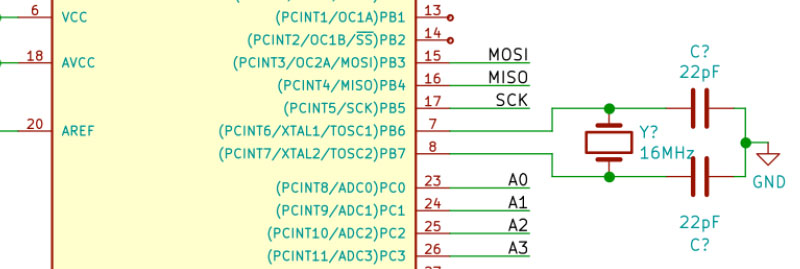
While working on a project for a friend, I got to thinking; it would be nice to have a checklist for circuit elements to include on a DIY Arduino board. In the early days, I forgot to add a filter cap to AREF, for example.
These tips are based on an 8-bit AVR design, like the ATmega328p chip. You could apply these tips to other 8-bit AVRs. Until now, I have not designed a custom board around a 32-Bit/ARM board. Though at only $16, I would be tempted to just solder the Teensy module directly to my finished board.
Below is a written list of items for a DIY Arduino checklist. If you’d like to see me design this board in KiCad, check out this AddOhms Tutorial.
A switching voltage regulator is one of my favorite circuits. In school, they were the first circuits I built where I understood how transistors worked. In fact, they were the first circuit I saw an inductor being useful! Switching regulators are incredibly efficient when designed properly. Of course, this detail about design is important. They are not as simple as a linear regulator, which is basically an IC and two caps.
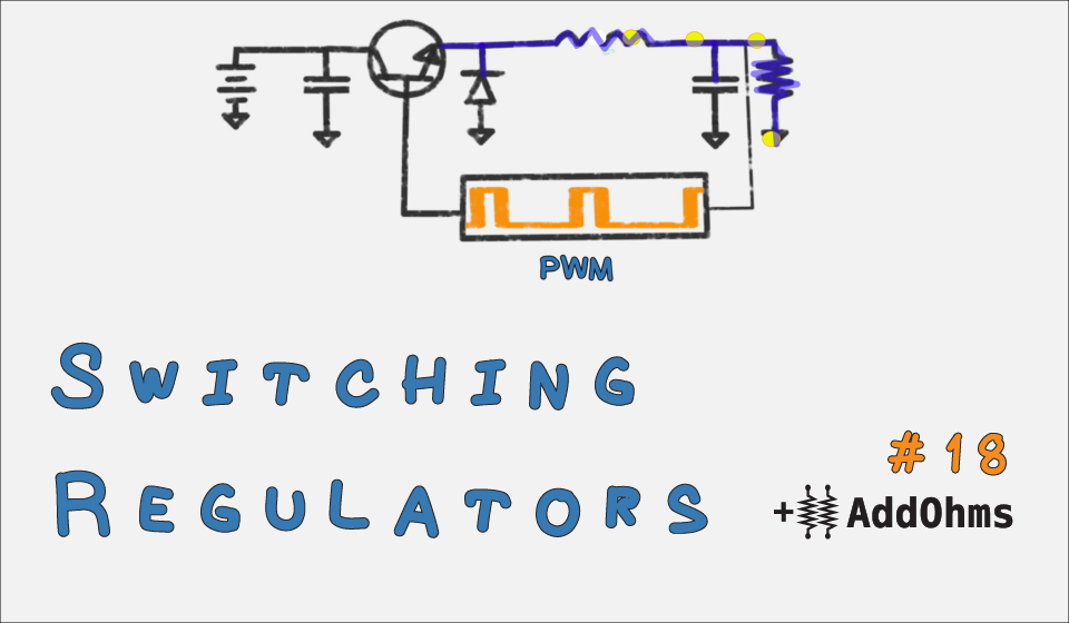
To understand the basics of a switching regulator, I released AddOhms #18 this week. This is video tutorial dedicated the Switching Voltage Regulator. If video tutorials aren’t your thing, then keep reading for my written tutorial.


