
Earlier this week, I looked at the Arduino MKR Vidor 4000 during an AddOhms live stream. My goal was to understand the Vidor better. It is the new FPGA-based Arduino which started shipping this month. It runs about $60. You can learn more at the Vidor Product Page on the Arduino website.
In this post, I briefly touch on the difference between an FPGA and a microcontroller. Then I walk you around the MKR Vidor 4000’s board. Using one of the examples, I talk a bit about how the various chips communicate with each other. This section also highlights what makes the Arduino FPGA board different from other development boards. Lastly, I answer “should you buy an Arduino MKR Vidor 4000?”
Original Live Stream
Before getting started, I need to mention that I have no inside information about this product. I asked some questions back at the 2018 Bay Area Maker Faire, but that was it. Everything in this post is what I learned from self-discovery. Much of the research for this post happened between this live stream and then follow-up work I did. Let me know in the comments if this kind of stream/video is helpful.
FPGA Introduction
FPGA stands for Field Programmable Gate Array. At a high level, you can think of an FPGA as a bunch of generic logic blocks with a matrix of interconnects. When you “program” the FPGA, you define how the blocks behave and the connections to each other.
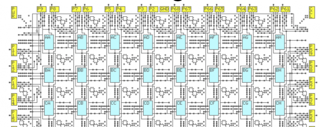
Related, Ken Shirriff has an excellent teardown of the Xilinx XC2064. It was the first commercially available FPGA. Download his slides for some fantastic die shots and explanations.
Modern FPGAs are far more sophisticated. For example, the Intel Cyclone 10CL016 FPGA used in the Vidor has 16,000 Logic Elements, 504 Kbytes (or bits?) of embedded RAM, and hardware multipliers for DSP operations. The pins can operate at speeds up to 150 MHz (sometimes called 150 mega-transfers). This particular part is well suited for audio and video processing.
FPGA vs. Microprocessor
The fundamental difference between an FPGA and a microprocessor is that in a microprocessor, the internal hardware never changes. The transistors have a specific purpose and specific connections. Now, it is common for multiplexers and internal switches to exist to make the chip more configurable. However, it is still a fixed function circuit. An FPGA, on the other hand, can be configured (and re-configured) to be virtually any digital circuit. In fact, a standard technique is to embed a microprocessor core inside of an FPGA design.
Bitstream, Schematic, VHDL
Historically, there were three ways people could program an FPGA. The first is to hand write, or hack, the bitstream. A bitstream is a string of bytes that configures the FPGA. Some users had to go this route with the first FPGAs. Back then, there were only about 64 logic blocks. (Check out the Ken Shirriff talk, linked above.) Another is to use a schematic editor. In that case, the user draws the design graphically. The process is similar to using EAGLE or KiCad, except, the design is limited to digital blocks. Those blocks might be counters, latches, flip-flops, and memory, to name a few. Lastly, high-level description languages (HDLs) exist, with two popular HDLs being VHDL and Verilog. Designing with HDLs is the most common method.
What makes the Arduino MKR Vidor 4000 unique is that it does not use any of those methods! Before talking about how it gets programmed, I want to look at the hardware first.
The MKR Vidor 4000
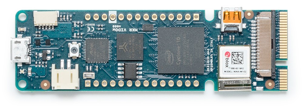
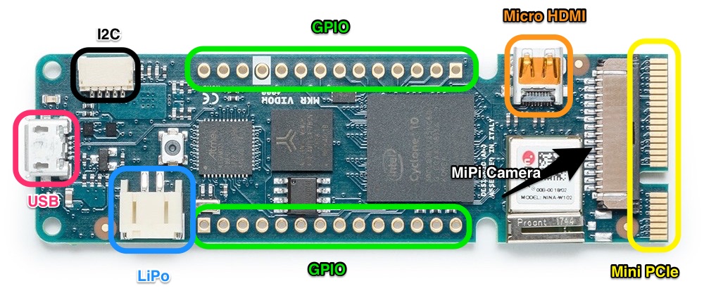
The board is smaller than I expected. It measures 83mm (3.25in) by 25mm (0.98in). There are plenty of ICs and connectors dotted around the slim board. The most striking connector is the mini-PCIe on one edge. In addition to it, there is a mini-HDMI, micro-USB, a mini-JST style header, a MIPI camera connection, and a LiPo connection. Oh, and of course, there are familiar looking I/O pin headers.
Here are some things I noticed and learned about some of these connections.
GPIO Pins
Based on the schematics, it appears the I/O pins of the SAMD21 are connected to some of the FPGA’s I/O pins, which are then connected to the header pins. This connection allows for communication between the two chips. (See the code below for the mapping between FPGA pins and the I/O headers.)
It does make mapping pins between the header and the FPGA a little bit strange. It would be nice if a table existed to match them up.
Mini-PCIe Connector
The edge connector is an industry standard. However, the actual signals are not PCI-Express. Instead, they are signals from the FPGA, the WiFi module, and the USB connector. Using this edge connector it would be easy to integrate the Vidor into a larger system design.
ICs on the MKR 4000
The board’s ICs threw me off at first.
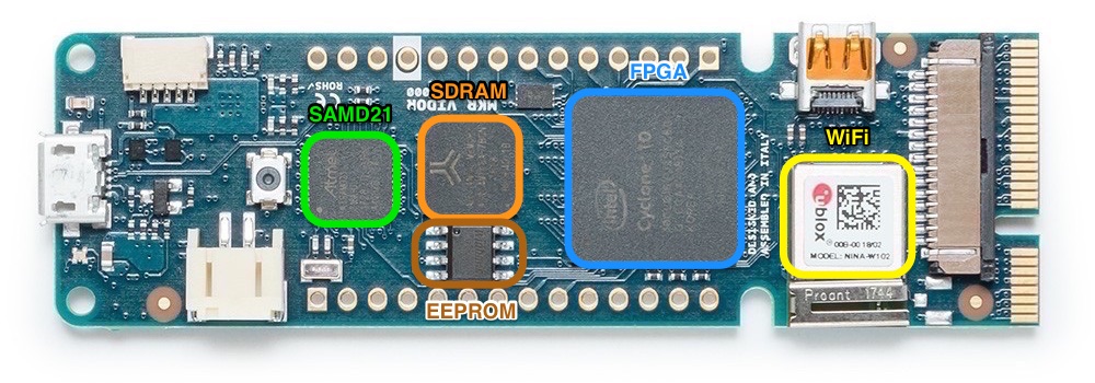
The big IC near the middle is the Intel (or Altera) Cyclone FPGA. The smaller square is the Microchip SAMD21 microcontroller. Looking through the MKR Vidor 4000 schematics, I initially thought the middle square chip was a power controller for the FPGA. Which would make it substantially larger than others I have seen, but hey, maybe! But no, I was wrong. It’s an EEPROM to hold the FPGA’s bitstream. And then I realized, I was wrong again. It is actually SDRAM.
There is an EEPROM for the bitstream, but it is the smaller rectangular chip. The chip between the SAMD21 and the FPGA is an 8 MB SDRAM! That’s a lot of memory.
Now that the chips are sorted out, let’s go and program something to the MKR Vidor 4000.
Setting Up the Arduino Vidor
The Vidor’s Getting Started Guide is the best place to start. (Go figure.) I will summarize the key steps: download the 1.90 IDE, install board support for the MKR 4000, and install some libraries.
Regarding the libraries, I suggest a search in “Library Manager” for the terms: “MKR” and “4000.” The libraries available will likely change over time. For this write-up, I am using the VidorPerpherials and VidorVideo libraries.
Vidor Blink Example
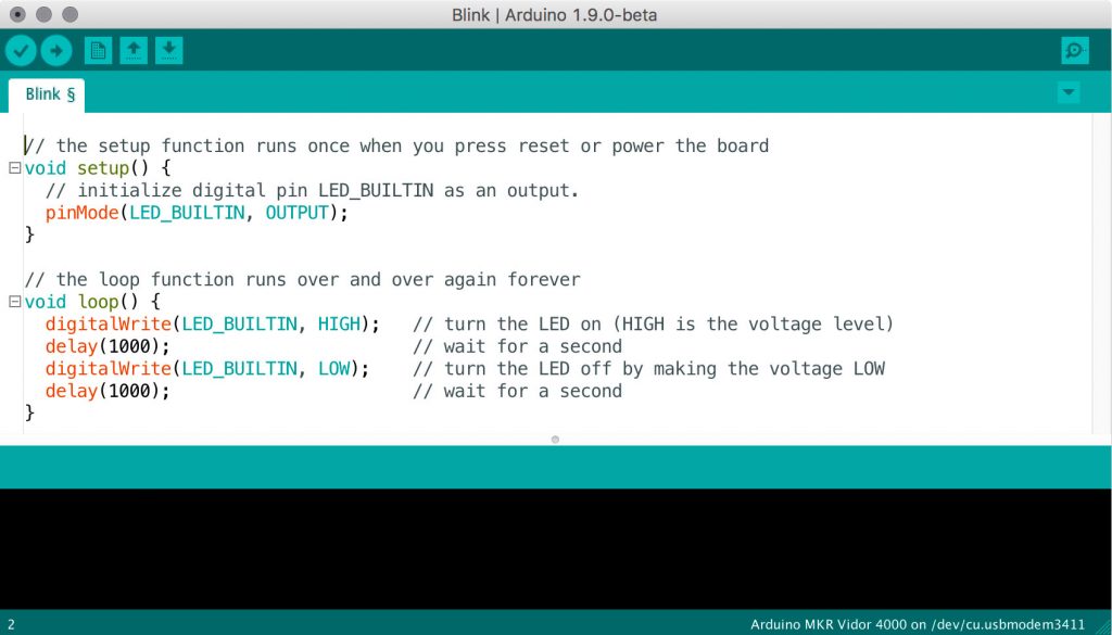
Once board support is installed, you’re ready to run the blink example. Just load the usual suspect from File -> Examples -> 01 Basic -> Blink. Hit upload and wait. If the red LED blinks, you are in good shape. (For an extra measure, I always change the delay() values to make sure everything is working.)
Wait, is this FPGA code C? Arduino? VHDL?
You might be looking at the screenshot above and notice that it looks suspiciously like C, C++, or “Arduino” code. Well, that is because it is C++. So what gives? Well, the blink example does not program the FPGA! Instead, it is only programming the SAMD21 on the board.
You see, the Vidor is a combination of two digital systems. The code you write in the IDE is primarily targeting the SAMD21. If that is the case, how do you access the Cyclone FPGA?
Vidor Block Diagram
Even though the schematics are available (download link), I put together this simple block diagram to illustrate what is going on.
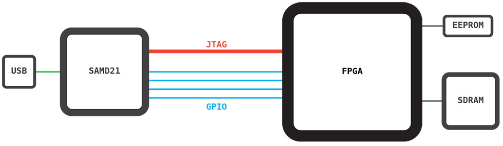
Like most FPGAs, the Vidor’s Cyclone powers-on blank. It loads its bitstream from the EEPROM. The device side USB port is connected only to the SAMD21, not the FPGA. (Note, the USB data lines are also connected to the Mini-PCIe connector AND some power control ICs. It is not clear to me yet how the host PC chooses which it communicates with: the SAMD21 or the PMICs.)
How does the FPGA get programmed?
Looking closely at the schematic, there are JTAG connections between the SAMD21, the WiFi Module, and the FPGA. Using the SAMD21 as a JTAG controller, the host PC can re-program the FPGA’s EEPROM.
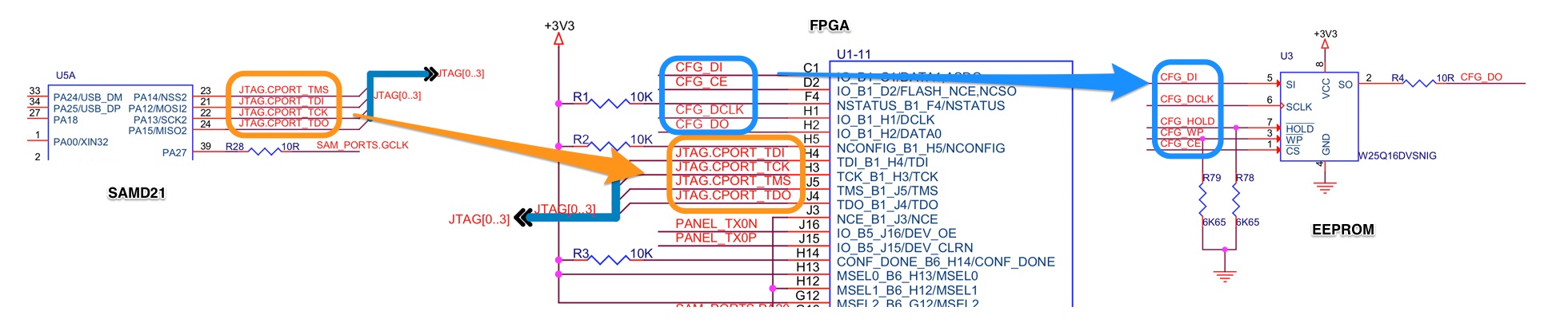
FYI, JTAG stands for Joint Test Action Group. It is an industry standard for interfacing, controlling, and programming chips.
From a user perspective, you might consider the Vidor’s FPGA a black box. It has a pre-programmed bitstream with some pre-defined intellectual property (IP) blocks. As of this writing, there is limited access for the user to modify the bitstream. In the future, a new graphical editor will offer a way to configure the FPGA differently.
The Arduino IDE can program the SAMD21 to communicate with the FPGA. Let’s look at an example.
VidorTestSketch
Looking at the code for this sketch, take note of the FPGA object. There are cases where the microcontroller is sending commands to the FPGA.
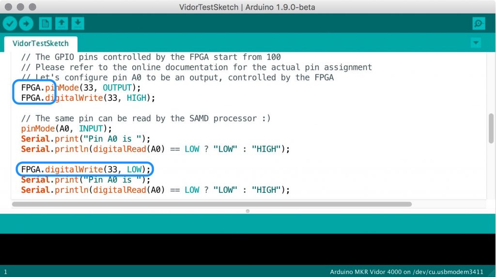
Notice how the sketch configures the GPIO pins on the FPGA, toggles them, and reads the states on the SAMD21.
My assumption is that the SAMD21 is sending commands over JTAG to the FPGA and its current configuration understands them. So it is possible to configure things like the I/O pins on the FPGA from the SAMD21’s (or Arduino’s) code.
Going through this example only touches on the capabilities of Vidor. But I hope it is enough to understand what the Vidor is.
Vidor Logo Sketch
Before I close, I wanted to mention a sketch that only requires an HDMI connection and is a cool demo. (Okay, you may also need a micro-HDMI adapter.) Load the VidorLogoDraw. It uses some Graphics library primitives to draw the Arduino Logo.
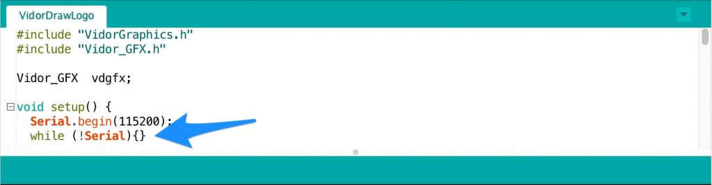
The catch to make this sketch work is that the SAMD21 does not send the GFX commands until you open the Serial monitor. Hook this one up and enjoy a simplistic rendition of the Arduino logo.
Where to go next?
If you’ve picked up a board, and have questions, you probably want a place to get answers. I recommend the MKRVIDOR4000 sub-forum on the official Arduino forums.
Is the MKR Vidor 4000 worth buying?
Immediately after doing my live stream, someone asked me if it was worth buying the Arduino Vidor. As with most purchases, there are a few considerations.
Let me start with why you might not want to buy it. First would be, you aren’t interested in FPGAs. That is an easy qualifier. Next, I would look at your experience level with FPGAs. The Vidor’s toolchain is not meant for development of custom Verilog or VHDL blocks. It is not a generic development platform for generic FPGA programming. While that process is possible, that is not the intended audience. (Though I do hope experienced FPGA designers will contribute blocks.)
However. If you want to explore the applications where you can use an FPGA without dealing with the complications of a strange toolchain, then yes. Get the Vidor. You can learn to connect blocks together, offload tasks from a microcontroller, and understand the capabilities of an FPGA platform.
As of this posting, August 2018, the board is best suited for early adopters. However, if you have any interest in learning FPGAs, it needs to at least be on your wishlist. (If it isn’t already in your shopping cart.)
You can learn more at the Vidor Product Page on the Arduino website.


9 Comments
Hi! I stumbled upon this article and saw your live stream and found it very informative. A great format. I am a newbie maker enthusiast with a background in audio engineering and software development. I bought the Vidor out of curiosity for FPGA’s, which I’ve never dealt with, and with an ambition to explore what they could be used for. Maybe in the DSP domain for audio and video. I sort of hoped that the Vidor could help my introduction to FPGA’s, but I think I might have been betting on the wrong platform for that purpose. I would love to see an introduction to FPGA from a simple digital systems approach, like why is this cool, and how do I approach a problem from an FPGA perspective. By now there seems to be a lot of initiatives for the Vidor, and there seems to be ways to program the FPGA, but it feels like they kind of expect a certain level of knowledge to enjoy, and for a newbie like myself, it’s hard to filter out the relevance. Any chance you could do a follow up on the Vidor, where the land lies right now, and maybe elaborate a bit more on how to customize the FPGA.
Thanks for a great article and stream.
I don’t have a plan to revisit the Vidor. I’m disappointed at how little development the Arduino team did with the platform since its launch. If you want to learn FPGAs, I would recommend looking at TinyFPGA. They’re open source boards with good community support. (and they are cheap.)
Got my Vidor and have watched your live stream. Thanks for this gentle introduction.
The FPGA pins are supposedly rated at over 150MHz. Is that the GPIO pins, or the PCIe pins? not sure.
There are fancy ADC’s that work up 150MHz. In theory, you could use the FPGA for basic DSP filtering, then pass data back over USB – or just decode in the microcontroller.
That’s actually qui8te practical.
I don’t think you’re going to get 150 MHz out of 0.1” header pins. I’d imagine the “full speed” pins are on the PCIe connector.
Catching data from a ADC and doing some first order DSP is a common use for FPGAs.
I guess the ADC on Cyclone 10LP is rated to 1 MSPS
That’s why you need a good external bus if you want to capture high speed data. 120M to 150M samples / sec is what separates the adults from the children.
Hello. I’m a “keyboard warrior” after having read this: gumstixgadgets.blogspot.com/2018/05/of-fpgas-and-arduino-mkr-vidor-4000.html 🙁
That article is full of opinion and limited on facts.