
The last time I looked at using an X-Carve for Printed Circuit Boards (PCBs), I created a demo board with EAGLE. Since then, I have learned more about using KiCad, the open source electronics CAD suite. While not a step-by-step tutorial, here is my rough KiCad to X-Carve PCB workflow. These are just the high-level steps, the tools necessary, and the settings I’ve discovered for each—so far.
Eventually, I will make this a more detailed KiCad to X-Carve PCB tutorial, so make sure you subscribe to my RSS feed for updates.
Here’s the Basic Steps:
- KiCad: Draw Board
- KiCad: Plot Gerbers
- KiCad: Generate Drills
- pcb2gcode: Generate G-code
- Text Editor: Clean Up G-code Files
- Camotics: Simulate G-code
- ChiliPeppr: Send G-code and control X-Carve
- X-Carve: Make the boards!
The Board: Adapter for Microchip MRF24J40MA
For some upcoming DIY home automation projects, I need wireless connectivity. Last week’s ESP8266 post was my first look at WiFi options. Next on my list is IEEE 802.15.4, or ZigBee, radios. For now, I’m working with a MRF24J40MA-I/RM Microchip IEEE 802.15.4 module, available on Mouser for ~$10.
Since the module is meant to be surface mounted, I decided to make a breakout board to make prototyping easier.
Over on the Pinguino Wiki, I found a KiCad board design for the MRF24J40MA. Perfect!
This simple breakout has a couple of pin headers, traces, a few “vias”, and an outline. These simple features make it a perfect board for testing a new KiCad to X-Carve PCB Workflow.
Tools to go from KiCad to X-Carve PCB
- KiCad (pcbnew, gerbview)
- pcb2gcode and pcb2gcodeGUI
- Text Editor (I use Sublime Text)
- Camotics
1. [KiCad] Draw (or download) the PCB
I’ve got the board file, so I didn’t need to do much in pcbnew. I did add an additional board outline on the Edge.Cuts layers.
There are two key layers:
Layer for Copper (Front)
This layer includes the Traces, Pads, and a “trace” outline. Leaving an outline on the Copper Layer a physical visual indicator to the board’s edges and where the end mill would be cutting later.
If you deselect or select layers in the PCB viewer, Pads are not included in the graphic viewer. However, when the Gerber file is created, they will be generated.
Note, in my screenshots this layer is called Cuivre, French for Copper.
Layer for Outline
The Edge.Cuts layer contains a polygon for where the finished PCB will be cut out of the PCB blank. I wasn’t sure how to generate an outline of the copper layer in pcb2gcode, so this may be unnecessary. On the other hand, having this as a separate G-Code gives some flexibility.
2. [KiCad] Plot PCBs
The first step towards using KiCad to Mill PCBs is generating Gerber files. This step generates two Gerbers: Copper Layer and the Outline Layer.
Based on older terminology, KiCad calls this process “Plot” under the file menu. These are the settings I used to generate my Gerbers.
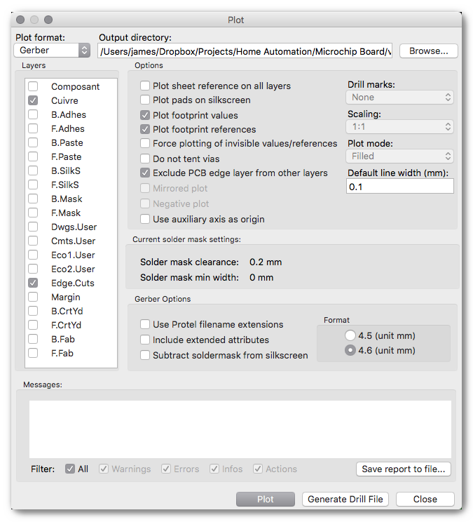
Make sure you:
- Verify the Output directory
- Select Copper and Outline layer
- Exclude PCB edge layer from other layers
- Format: 4.6 unit mm
- Deselect the 3 Gerber options
Click the “Plot” button when ready. After plotting finishes, keep the window open. There is one more button to click.
3. [KiCad] Generate Drill File
From the Plot Window, click “Generate Drill File” to open Drill options. Again here are the settings that I used in my setup.
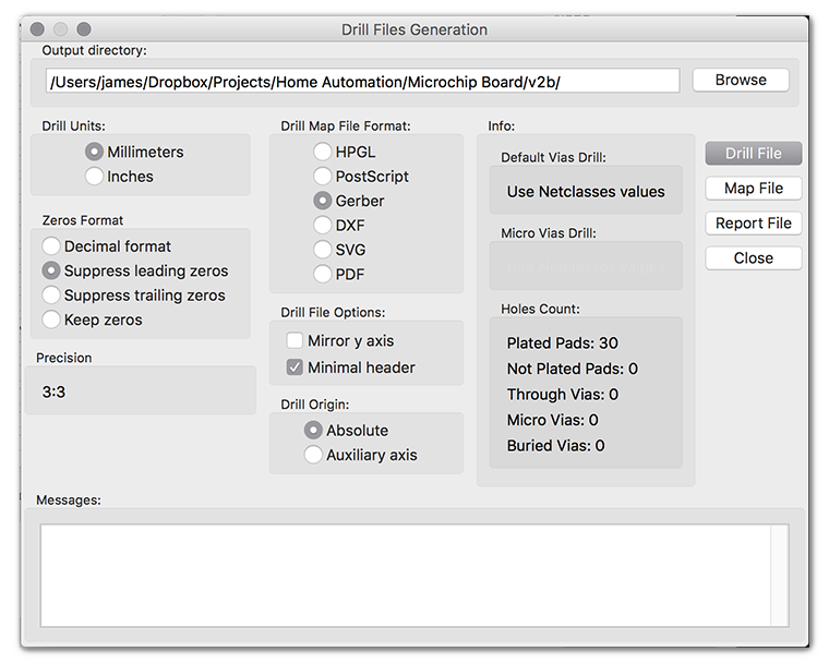
On this screen:
- Double-check the output directory (should carry over)
- Set units to millimeters
- Zeros Format: Suppress leading zeros
- Unselect both Drill File Options
- Make Drill Origin Absolute
Two notes:
- I think both inches and millimeters work, but I only tested a real carving with millimeters.
- The Drill Map File Format is irrelevant.
Once you click “Drill File”, the message area will be updated with the new drill file. Now you can close both the Drill and Plot windows.
At the point you’ll have at least two gbr files and one drl file. KiCad includes a Gerber viewer named gerbview. Use this tool to see what the Gerber files look like, visually.
gerbview: Unexpected Symbols
 If you try to double-click on the drill, or drl, file you may get an error about “Unexpected symbols.” You might also get a dialog that says:
Warning: this file has no D-Code definition
It is perhaps an old RS274D file
Therefore the size of items is undefined
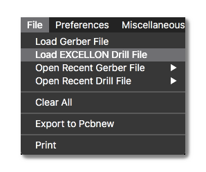
It will also appear gerbview is showing the drill file as blank! Uh-oh…
There’s nothing wrong with your drill file. You just need to tell gerbview to load the file as an EXCELLON Drill File, available in the File Menu.
Now that we are done with the Gerber and drill files, time to create the G-Code.
4. [pcb2gcode] Generating G-Code
Here’s the good news. pcb2gcode generates the G-Code needed to drive a CNC like the X-carve. Here’s the bad news, if you aren’t running Linux it can be a bit of a pain to get it up and running.
The GitHub README has information on Linux and Windows. But nothing about how to install for Mac. I’ll come back to that in a later post. For now, you’re going to need Windows or Linux for pcb2gcode.
Running pcb2gcode
There are a ton of command line options for pcb2gcode. Until you get use to using the program, I highly recommend pcb2gcodeGUI. If you get pcb2gcode compiled and running, the GUI is no problem.
Using pcb2gcodeGUI, here are the settings I used. You should be able to translate these into the command line settings if you can’t run the GUI.
Common Settings
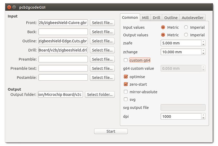
Main things to set:
- Set the Front (Copper) Layer
- Outline (Edge.PCB)
- Drill File
- Uncheck G64, if checked (more on that later)
- Check Optimise
- Check Zero-Start
- Uncheck mirror-absolute
That’s it.
Mill Settings
These settings directly affect how the X-Carve will mill the traces (or the isolation paths around the traces.) Depending on your mills, or bits, you may need to tweak these settings.
I left mine with the pcb2gcodeGUI defaults:
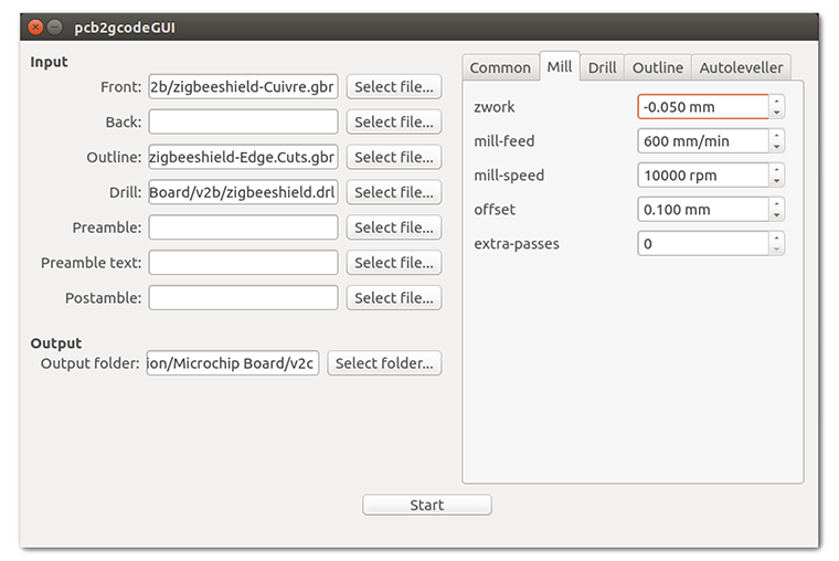
While testing, I did slow the mill-feed down to 100 mm/min. I wanted a little slower while I watched for issues.
Drill Settings
When it is time to drill any through-holes or vias, these settings will be used.
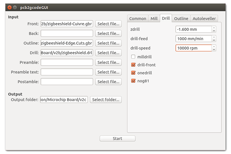
- Z-drill is how far to drill down. Make sure this is at least as thick as your PCB material and slightly deeper. You want your drill to go all the way through to your waste material.
- Set drill-front
- [Optional] Set onedrill
- [Important] Set nog81
X-Carve is based on an Arduino running the simple G-code interpreter grbl. It does not support the tool change command, so I decided to keep all of my holes the same size.
The G-Code G81 is used to simplify G-code instructions. It is a way to repeat drilling on the z-axis, with single commands. Sadly, grbl does not support G81. Enabling “nog81” causes pcb2gcode to generate the necessary discrete commands.
Without “nog81”, the X-Carve will just move on the X and Y axes without drilling any holes.
Outline Settings
The default pcb2gcodeGUI settings for the Outline needed significant changes.
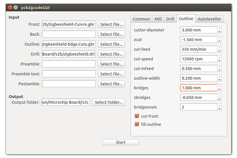
Here’s what I used, and I’m still not happy with them:
- Cutter-diameter is the size of your end-mill. Make sure you are using an “end mill”.
- Zcut is the thickness of your pcb material. This will probably be the same as your zcut from the drill section.
- Cut-feed is how fast to move the tool. I slowed my down to 250 mm/min. I might go slower on my next board.
- Cut-infeed sets how deep the mill cut on each pass. The default was 10mm, which meant, the outlook would be cut on a single pass. I changed to be a fraction of my end mill’s diameter. This means multiple passes, but longer lasting end mills.
- Bridges are also known as tabs. This sets the width of the bridge. See my note below.
- Zbridges determines the z-height when going over the section for a bridge. See my note below.
- Bridgesnum is straight forward, how many tabs do you want when the outline is cut. Definitely a minimum of 2. I have a Dremel handy, so 4 doesn’t bother me.
With pcb2gcode version 1.2.2, there is a bug in the z-bridges. However, a commit to the git repository has already been made, so it might be resolved. Will update once I have a chance to verify.
Generate the G-Code.
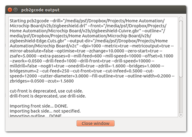
Click Start to call pcb2gcode, which generates the G-code. Take note of the information in the dialog. Save the provided full command line for future reference!
You should now have three files with NGC extensions, full of G-Code.
5. [Text Editor] Cleaning G-Code Files
Even though pcb2gcode does a good job of cleaning up G81 for grbl, there are still some left over commands that cause it to complain.
For information on what these G-Codes mean, check out this G-Code Quick Reference Guide from LinuxCNC.org.
What to remove from Drilling File
Open up the drilling G-Code’s file. Remove the M6 command, since grbl doesn’t support tool changes. Also, remove the M0 command.
Lastly, remove the M2 command near the end of the file. It’ll make moving on to the next G-code file easier.
Remove G64 from each Milling File
Both the Front/Copper and Outline files will have a G64 command.
This G-Code does some fine tuning, but grbl doesn’t support it.
Like the drilling files, remove the M2 command. Otherwise, grbl will need a reset when finished with the file, making re-homing difficult.
By removing M2, you should be able just to reset the Z with each bit change.
6. [Camotics] View the G-Code
The last step before warming up the X-Carve is running Camotics. This tool is an open source G-Code Viewer or simulator. It visualizes what milling/drilling will be done, and gives you an idea of the tool’s path.
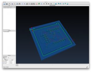
You can also load all 3 (or 4 if two-sided) files at once, to make sure everything appears to visually line up.
7. [ChiliPeppr] Send the G-Code
Ready to make a board? Yeah, so am I!
There’s a couple of options for sending the G-code file to an X-Carve. The default option is the online Easel software from Inventables. To me, this is a good “getting started” software and good for general purpose engraving.
For direct control I prefer ChiliPeppr Hardware Fiddle. It is a web-based tool that does 3D visualization, provides direct control, and sends G-Code. You will need to install a small local client to provide the serial communication.
There is a workspace specific to grbl: chilipeppr.com/grbl.
Just drag and drop your files into Chilipeppr. Once there, use the “play” button to send your G-code.
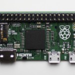
(In the future, I plan to dedicate a Raspberry Pi for this purpose.)
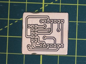
8. [X-Carve] Make the boards.
Hopefully, you have limit switches, so you can home the X-Carve easily. I routinely home a CNC, zero the axes, move the bit to my 0,0 and record the location. If something fails and I need to start over, this gets me much closer to “my home” than trying to eyeball it.
Here’s the board order, with bits that I used.
Front/Copper Traces
For traces, I used a tapered PCB bit from Inventables. PCB blanks aren’t known for their flatness, so it took several passes to mill through the entire copper. On each pass, I dropped my Z between 0.1 and 0.5mm until all of the traces cleanly cut.
Drilling
Next I ran the drill file with my 1.0mm drill bit, included in the PCB Drilling Bits also from Inventables.
Outline
Last is the outline.
You could try to cut in a single pass and let the tabs stay, but I didn’t like loading my bit with that much material.
And… done!
Going from KiCad to X-Carve PCB
This workflow is complicated, but functional. As I get more experience with both KiCad and my X-Carve, I will be providing updates.
For now, any suggestions on how to improve the workflow?
2 Comments
Great article. You need to make a vacuum table center, like an air hockey table has. Drilling a fine matrix of holes in the center of the table, and fitting a vacuum cleaner to the bottom would suck the board flat.
http://frankpiesik.org/2014/11/24/my-pcb-milling-toolchain/