Category

Blog

Category

The last time I looked at using an X-Carve for Printed Circuit Boards (PCBs), I created a demo board with EAGLE. Since then, I have learned more about using KiCad, the open source electronics CAD suite. While not a step-by-step tutorial, here is my rough KiCad to X-Carve PCB workflow. These are just the high-level steps, the tools necessary, and the settings I’ve discovered for each—so far.

Eventually, I will make this a more detailed KiCad to X-Carve PCB tutorial, so make sure you subscribe to my RSS feed for updates.

Here’s the Basic Steps:

  1. KiCad: Draw Board
  2. KiCad: Plot Gerbers
  3. KiCad: Generate Drills
  4. pcb2gcode: Generate G-code
  5. Text Editor: Clean Up G-code Files
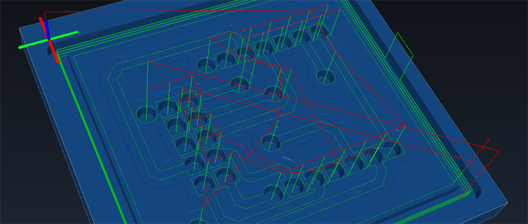
  6. Camotics: Simulate G-code
  7. ChiliPeppr: Send G-code and control X-Carve
  8. X-Carve: Make the boards!

gCode Viewer: Camotics

A gCode viewer is essential when doing anything with a CNC. Knowing where the tools is going to run can mean the different between a failed cut and a broken bit. Or let’s say you’re trying to debug some gCode scripting, no need to wait an hour to find out you messed something up. That’s where a GCode Viewer can help.

There are several on-line options that let you upload files and see them in a 3D view. However, if your CNC is setup like mine, there isn’t a good internet connection available. Camotics, formerly the unfortunately named OpenSCAM, is a cross-platform open source gCode viewer / simulator.

Most recently I used it to debug some gCode that pcb2gcode generated from a Kicad board I am working on.

Check out more about Camotics on their site: http://camotics.org

Adding WiFi to any project can be difficult. There are a few off the shelf options that make it easier. One option is the official Arduino WiFi shield. This full-featured shield uses its integrated microcontroller to handle the WiFi protocol, security, and the TCP/IP stack for you. From “plug it in and go” perspective, this is an awesome option for Arduino-based projects. Plenty of example code supports the nicely designed hardware. The main downside to some people is the price.

The more popular option these days is the ESP8266, typically advertised around $5US. They are about the size of a TO-220 packaged transistor. How do they get so small? Using a technology known as “System On a Chip”, or SOC, these tiny modules pack everything on the Arduino WiFi shield inside of a single chip! SOCs are great when space is limited. If production volumes are high enough, there can even be a cost advantage.

After spending some time with an ESP8266 I bought on eBay (which I don’t recommend..), I’ve found some things you need to know before building your ESP8266 based project.

When you hear the name “Arduino,” does a picture of the Uno come to mind? While the most popular, this 8-bit based board isn’t the only Arduino available today. There are some other boards available like the Due and recently introduced Zero, which are far more advanced than the humble Uno.

These are 32-bit microcontroller boards that have a very different architecture compared to the relatively straightforward Uno. In fact, one of the most striking differences is that the Due and Zero have two USB ports.

What is the difference between the Programming and Native ports on these more powerful Arduino boards?