Tag

pcb

Browsing

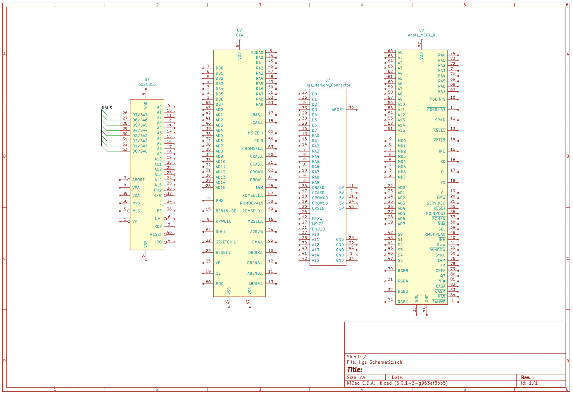
A new project I have started working on involves the Apple IIgs. It was Apple’s last 16-bit (and 8-bit) computer. Inside are many application specific integrated circuits, or ASICs, that make the IIgs an extraordinary member of the Apple II family. One chip, in particular, is called the “MEGA-II.” This chip takes all of the individual logic chips from the original Apple II design and incorporates them into a single 84-pin PLCC.

The project I have in mind needs the MEGA-II. I need to design some printed circuit boards for it and a few other IIgs chips. That goal means I need at least one custom Kicad schematic symbol. I plan to create a custom library of Apple IIgs components.

Like other computers from the same era, complete schematics are available. However, they are not in a modern format. Since I need to create symbols for so many of the chips as it is, I may end up re-creating the entire IIgs schematic.

For now, here is the process I use to create custom KiCad schematic symbols and parts.

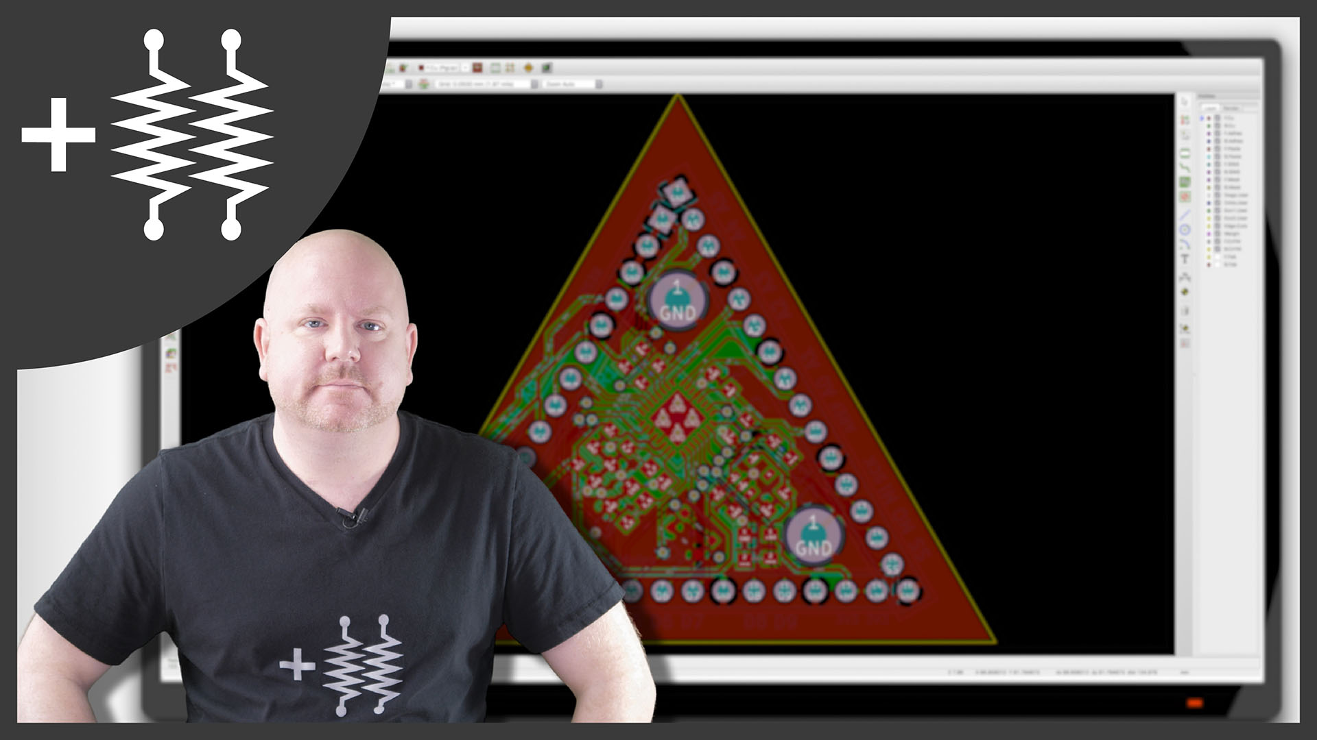
Continuing the DIY Arduino tutorial series, this AddOhms episode shows how to create a PCB in KiCad. I make a joke that the original design was a rectangle, which I found boring and pointless. So instead, I designed a triangle to give the board 3 points. Get it? Puns! I am calling it the Pryamiduino. To be honest, I found not having a constraint to be a problem. By forcing a specific board size and shape, many decisions were more manageable.

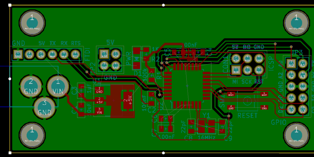
boring rectangular arduino nano clone
First design – Boring!

In the end, the video ended up more edited than I planned. KiCad is just so finicky and crashy that I could not make a coherent start to finish tutorial. At least, I could not work with a board at this level of complexity. Something simple like a 555 flasher would be easier to show from start to finish. I am planning some immediate follow-ups with quick tips on using KiCad. It is a frustrating suite of applications, but the results can be quite nice.

AddOhms Pyramiduino Show Notes
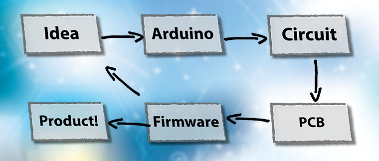
This week’s post is from my friend John Teel. I asked him to help answer a common question I receive: “How do you make an Arduino project into a product?” His experience as an electronics design engineer and serial entrepreneur is ideal to talk about going from prototype to product. He has developed tech products that sell in the millions of units. John now helps entrepreneurs, startups, makers, and small companies bring new electronic products to market. Check out the company he founded, Predictable Designs, and his free cheat sheet – 18 Steps to Market for Your New Electronic Product after reading his excellent post below.

Dreaming of bringing a new hardware product to market?  Perhaps you think your product will make the world a better place, or maybe you just dream of making millions of dollars.

Developing a prototype based on an Arduino (Genuino outside the USA), or other development kit, is a great first step.  But there is still much work to do if you want to make your product into something that can be manufactured in volume and sold to the masses.

So I’m going to break down the process for you into a few manageable steps:

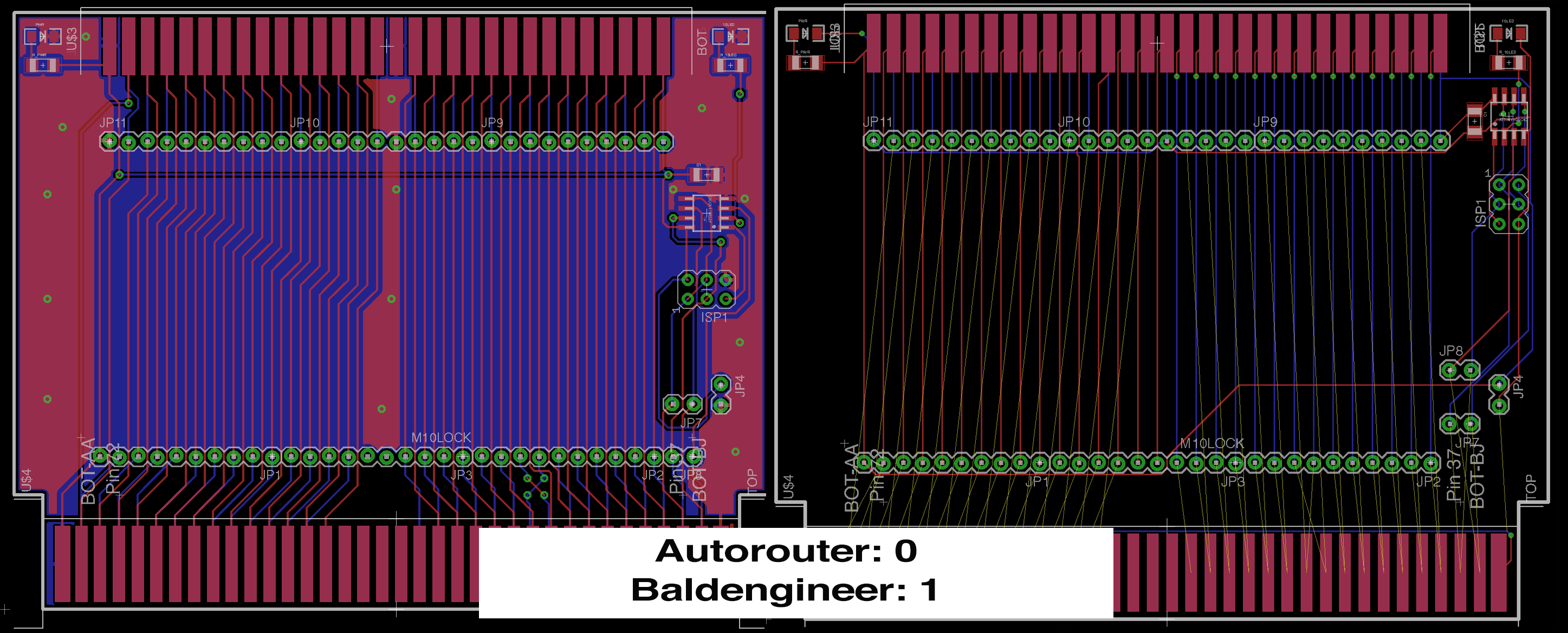
I am not a fan of relying on the Autorouter in EAGLE — or any PCB CAD software for that matter. When laying out a board, I’ll use the autorouter to get an idea if the part placement is going to work or not. In this case, I was reminded how much autorouters suck! Even after running for while, the autorouter could only route up 50% of the nets (signals).

Never Trust The Autorouter

As Chris Gammell‘s T-Shirt Says, Never Trust The Autorouter.

It only took me about 20 minutes to start over and finish the manual layout. I still want to clean it up a little, but over all, I beat the Autorouter.

What is the board anyway?

In January I visited Tokyo on my annual work trip. While there, I ran over to Akihabara to check out a used media store called Traders. The multi-level store (like all those in Tokyo) sold used video games and movies. Each floor featured different platforms. My favorite was the 2nd floor which was all retro 8, 16, and 32 bit systems. Piles of Famicoms (NES), Super Famicoms (SNES), Mega Drives (Genesis), and other systems were all around. In the middle of the floor were racks of cartridges.

While there I picked up a couple of Rockman (Mega Man) carts, Super Mario brothers, and even Adventure island.

A US-based NES can play Famicom games since the basic hardware is the same. However, the pin outs are slightly different. Also, US-based NES systems look for a lock-out ship (CIC) that Famicoms don’t have. Fortunately I ran across a project that uses the ATtiny (AVRCICZZ) to emulate the lockout chip. So armed with that and some pinouts, I’ve created an adapter.

Keep subscribed, after a few more touches, I’ll post the EAGLE files as an Open Source Hardware (OSH) project.

When you start creating your own parts in EAGLE, you’re going to want to store them somewhere.  Here’s how to setup EAGLE to use custom directories and how to create your own Library, which gets stored in the custom directory.  There are a number of steps involved, but once setup custom libraries give you a place to store components you create as well as the ability to copy other parts into your library.