
A switching voltage regulator is one of my favorite circuits. In school, they were the first circuits I built where I understood how transistors worked. In fact, they were the first circuit I saw an inductor being useful! Switching regulators are incredibly efficient when designed properly. Of course, this detail about design is important. They are not as simple as a linear regulator, which is basically an IC and two caps.
To understand the basics of a switching regulator, I released AddOhms #18 this week. This is video tutorial dedicated the Switching Voltage Regulator. If video tutorials aren’t your thing, then keep reading for my written tutorial.
Switching Voltage Regulator Introduction
There are two major types of Voltage Regulators: Linear and Switching. For a higher level introduction, check out my earlier Voltage Regulator Tutorial.
Linear regulators only need a small number of components, are simple to add to a board, but are not very efficient. Switching regulators can be made to be very efficient for a particular circuit, but can be difficult to design.
Back on AddOhms #17, we talked about how Linear Regulators work. In this tutorial, we are looking at switching regulators.
Switch-Mode Converter Core Components
There are 4 core components needed in a switching voltage regulator.
Capacitors
Capacitors store energy in an electric field. When a voltage is applied, the capacitor charges up. When the voltage goes away, the capacitor discharges.
Inductors
Inductors store energy in a magnetic field. When current flows through the inductor, a magnetic field is created. When the current stops, the magnetic field collapses generating current.
Switching voltage regulators work by making use of the energy storage properties of a capacitor and an inductor. To control the charge and discharge of these components, we use diodes and transistors.
Diodes
As we discussed in AddOhms #8, diodes only allow current to flow in one direction. Later, we’ll see what that is important.
Switches (or Transistors)
The switch or transistor used to control the regulator is why we call them “switching regulators.”
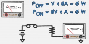
When the switch is “off” no current flows through it. No current flowing, means no power wasted. When the switch is “on” the voltage drop across the switch is 0 volts. So again, no power is wasted. Typically a MOSFET is used for the transistor, however, it is possible to build a converter with a BJT.
Now that we have all of the components let’s combine them together.
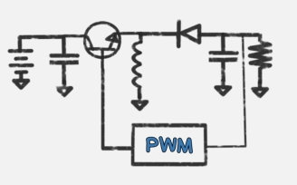
Buck Converter
A buck converter, also called a step-down converter, will create an output voltage lower than its input voltage. This is similar to how linear regulators, like the LM7805, work.
The inductor tries to keep current flowing while the capacitor tries to keep the voltage constant. When we connect the inductor to the capacitor, the inductor becomes a current source, and the capacitor becomes a voltage source.
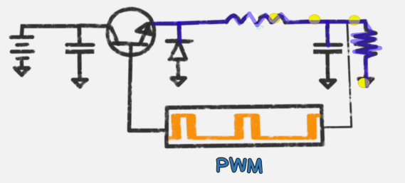
The transistor is used to control the charging and discharge of the inductor. For example, you could use Pulse Width Modulation to control how long the inductor is charged and discharged.
In an ideal circuit, all of these components would have no power loss. In reality, these all burn a little bit of power, which is known as switching losses.
However, compared to a linear voltage regulator, this switching circuit is much more efficient.
Boost Converter
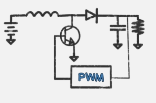
Unlike linear regulators, switching regulators can create output voltages higher than their input. These are called boost converters. Because they, boost or step-up the output voltage. A boost converter uses the same components as a buck converter, just in a slightly different configuration.
Buck-Boost
A third type of switching converter, is a ‘Buck-Boost” configuration. This circuit boosts a low input voltage and bucks down a high input voltage. There are several types of buck-boost converters. The one drawn here is an inverting buck-boost. Two other popular types are the Single-ended primary-inductor converter SEPIC and Ćuk converters.
These are commonly used on battery circuits to extract the maximum energy possible from a battery.
Integrated Circuits
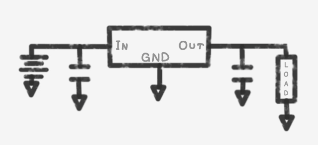
Normally, an integrated circuit, or IC, is used for a switching regulator. It contains the switch and the PWM controller. An example is the LM3671 Buck Converter from Texas Instruments.
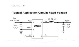
The simplified schematic shows input capacitors, output capacitors, and an inductor. Even though this looks simple, a switching regulator is much harder to design than a linear regulator.
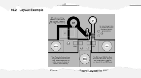
Designing the PCB takes much care. In this case, TI provides a very useful layout recommendation in their data sheet, plus lots of information on how to pick components.
Pre-Made Modules
What if you do not want to go through that much effort? Well, you can buy pre-made switching modules that are simple as Input and Output pins.
For example, Adafruit offers pre-made modules for buck, boost, and buck-boost.
Conclusion
The high efficiency of switching regulators makes them ideal for high current applications or projects that run on battery. What has been your experience with using or designing your own switching power supplies?
I’d also like to hear any questions or tips you have for DC-DC converter design. I might use them in a future post (or video).


7 Comments
Pingback: An Introduction to Basic Electronics
Dear Sir,
I want to measure capacity of a battery, with different loads. So I designed a voltage divider/down scale to get max 4.5 volts across a resistor, which is fed to Arduino to take reading. The problem is that when battery voltage is more or load resistance is less, voltage fails to vary voltage fed to Arduino between 0 to 4.5 volts, it is going beyond 5 volts. Arduino might get damaged If the voltage raises above 4.5volts.
So, as Arduino analog pin takes input in the range from 0 to 4.5 volts, I want a voltage divider to proportionally down scale battery output voltage ranging from 0 to 20 volts….same condition want to achieve with variable load.
Then you have to design your voltage divider for a maximum of 20 V. You’ll end up with about 4:1 divider.
Keep in mind, if your batteries are Lithium Ion or Polymer, voltage is a lousy indicator of capacity remaining.
Dear Sir, Thank you very much for the reply.
How to get 4:1 ratio with different watts loads? this is where I stuck.
I am want a electronic circuit which should be flexible enough handle different watts of load and varying input voltage.
Thanks and regards,
Dayanand Shahpurkar
Bangalore, India.
You don’t. A voltage divider is not a regulator. If the output is driving a changing load, you do not use a voltage divider.
Texas Instruments also do a free circuit simulator, so you can blow things up virtually before committing to real components.
http://www.ti.com/tool/tina-ti
One thing to be careful of with switching supplies is that they can generate electrical noise for both the output but also the input.
This could be important if you are measuring small signals, have audio outputs or high speed communication.