
For an AddOhms series, I created a DIY Arduino I am calling the “Pyramiduino.” It is an ATmega328p based board in the shape of a triangle. Other than being cute, the shape does not offer any other benefit. The design features a 3.3 volt LDO Regulator, which is also the subject of this post.
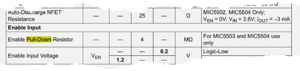
I forgot a fundamental aspect of design: read the freaking datasheet. The board’s LDO regulator was not turning on. Adding a passive scope probe to the circuit suddenly fixed the problem. The regulator turned on. When touching the enable pin, it measured about 1.25 volts. While I am sure Rohde & Schwarz would like me to ship scope probe with each board, that was not an option. With the impractical fix in place, I got to thinking about that voltage level. I remembered that the datasheet mentioned about 1.2 volts was needed for the “HIGH” threshold. Which meant, 1.25 volts applied to the pin enabled an active low input. Not only that, I remember the datasheet clearly said it had a pull-down resistor built-in. What was going on?
My Mistake
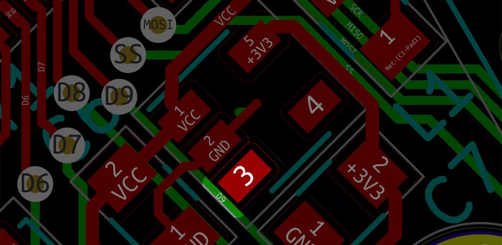
One day I am going to build a library of standard parts I use in all designs. That way, I do not confuse myself with bits of new knowledge. Until then, my current method is to go to Digi-Key, filter by in-stock, and sort by price. At least, for most components. That is how I found the Micrel (now Microchip) MIC5504. It is a 3.3 volt LDO Regulator with an output capability of 300 mA. It comes in a SOT-23-5 package, which includes an enable pin. I checked the datasheet to see how the enable works and saw the following description.
See the problem? If not, here are five things I learned you need to consider when picking an LDO Regulator. These characteristics go beyond the voltage ranges and current capability. The answer to my board’s problem is on this list.
1. LDO Regulator Packages: Small Transistor Outline (SOT)
When picking an LDO, it is widespread to see them in a SOT package variant. You might see package names like SOT-223-5, SOT23-3, and the SOT23.
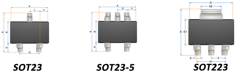
SOT23 vs. SOT23-5 vs. SOT223
The SOT23 is a 3-pin package common for discrete transistors and diodes. A variant, the SOT23-5, is used for ICs, including voltage regulators. You might also see the industry name, set by JEDEC, which is TO-236AB.
A larger version is the SOT223 and SOT223-5. The SOT223 is a 4-pin package, which is why it is sometimes labeled “SOT223-4.” The SOT223-5 is a 7-pin package! Just kidding. The SOT223-5 has 5 pins.
Technically one pin of the SOT223 packages is a tab. These help with creating a heat sink from the internal silicon to the external PCB. Despite this feature, I chose a SOT23-5 package for my design. I wanted the smaller package, and I wanted an enable pin.
2. LDO Regulator Pinouts aren’t the same
I know, the obvious statement is obvious. However, if you only look at a few LDOs with similar packages, you might quickly assume that the pinout is the same for all of them.
In my comparison research, I found seven 3.3 volt LDO regulators with at least 300 mA current capability. Of those, most of th epins were in the same place. But that does not mean you can just glance at the pinout and say “Oh, the output is pin 5” and then assume everything else is where you expect it.
Even if the pin names or functions match, there could still be differences. In my case, those differences caused a headache in the finished Pyramiduino design.
3. NC, Bypass, and Adjust
Across the seven LDO regulators I surveyed, I found four functions for the “extra” pin. They were either a no-connect, reference bypass, or the adjustable input.
- No Connect (NC) means what it says. It is not necessary to connect the pin. Pay careful attention to the datasheet. Sometimes the chip’s designers say: “do not connect to anything, including ground.”
- Reference Bypass improves the ripple rejection for the output. An LDO regulator that breaks out the internal voltage reference to a pin, offers you the chance to add a tiny value capacitor. This filter capacitor can improve the regulator’s response. Regardless of what the data sheets suggest, I would only use a C0G type ceramic capacitor here.
- Adjust input is only available on regulators with an adjustable output. Instead of a fixed internal feedback look, this pin lets you feedback the output through a voltage divider. This divider sets the output voltage for the LDO regulator. Sometimes data sheets recommend a small value capacitor in this network to help with ripple rejection. Follow their guidelines.
- MCP1824 Only: Power Good provides a signal based on the enable pin. The datasheet goes into depth about how it behaves.
Even considering “power good” as an oddity, I do not think any of those functions are a surprise. FYI, in most cases, it is safe to leave a bypass-pin unconnected. The pin that surprised me is the enable pin!
4. Not all LDO Regulator Enable pins are the same
On a past LDO-based project, I noticed that LDO regulator data sheets would sometimes refer to a pin as either “enable” or “shutdown.” A Vinculum, or bar, above “shutdown”, indicates its active low status. I just assumed the terms were interchangeable.
After reviewing seven different LDOs, I did notice there could be a slight difference between how “enable” and “shutdown” work. Six of the seven LDOs specifically described how the regulator behaviors when disabled.
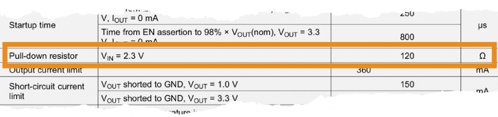
When disabled, most LDOs connect the output pin to a resistor connected to ground. This path discharges the output capacitor(s). Different datasheets call out the value of this resistor differently. Curiously in the TI TLV733P, it is called a “pull-down resistor.” Grammatically that name makes sense. I do think it could confuse some people because most of us associate pull-down with inputs, not outputs.
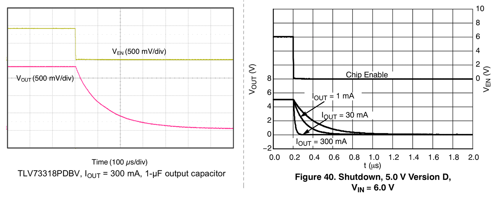
A datasheet will either give you a value for this resistor, which seems to range in the 25-150 ohm range, or it just provides graphs. The left graphic above is the most common I saw. If you know what capacitor charge and discharge graphs look like, it looks pretty familiar. However, RC curves are dependent on both the resistance value and the amount of capacitance. So your output voltage, the load connected, and the size of the capacitor affects the curve.
In this batch, the only LDO regulator to show different curves is the ON Semiconductor NCP4625. The right graph shows different curves for VIN and VOUT, along with different IOUT currents. (I am only showing one of the VIN-VOUT graphs there.) This behavior and resistance value is something to keep in mind in your design.
Come to think of it. This resistor could be why injecting power into a node connected to a regulator’s output is a bad idea. I’ll have to come back to that in the future.
5. Pull-down Vs. Floating
Pull-up (and pull-down) resistors are something I have covered quite a bit. Including, how to pick their value. When it comes to the LDO regulator’s enable, or shutdown, pin different manufacturers handle the pin’s unconnected state differently. Some chips include a pull-down resistor, like the MIC5504 I picked and some require you as the user to handle it.
This feature alone means you should take care when replacing a regulator in a design. If the old regulator had a pull-down built-in, you need to make sure the new one does not leave the signal floating. In the seven I looked at, only the MCP1824 never mentioned whether or not you should include a resistor. The clue is that the performance curves have a note about using an external 10 Kohm resistor.
In cases where you do not care about the enable function, you can tie the pin to the input voltage and forget about it.
Oh yeah, my mistake
Now that I have gone through those five LDO regulator considerations, I need to come back to what I screwed up. When I read the MIC5504’s datasheet, I only looked at the electrical characteristics. I did not even bother to read the first page. (Why would I? It is just marketing fluff anyway, right?) The pin description table tells a different story. However, it was too late.
When I read “enable pull-down resistor,” my brain said, “oh, the enable pin is active low.” At the time, it did not occur to me how stupid that statement sounds. Why would a regulator with an enable pin, permanently enable it? If you do NOT care about the enable, you might use a SOT223 or SOT23 package which does not include the pin. If the pin is there, connecting it to VIN is not an issue. Traces on a PCB are free.
An LDO regulator enable-, or shutdown-, pin only exists in situations where you want to disable it.
The genesis of this post was from me looking for SOT23-5 LDO Regulator with active-high enable connected with an internal pull-up resistor. After about an hour and a half on Digi-Key, I realized this unicorn does not exist. And it should not.
Lesson learned, read the entire datasheet. A secondary lesson, consider why pin functions exist across manufacturers.
LDO Regulator Links
Here are the seven regulators I used in my comparison. The MIC5504 is the one I used in the design.
- Diodes, Inc AP2127
- Exar Corp SPX3819
- Microchip (Micrel) MIC5504-3.3YM5
- Microchip MCP1824T-3302E
- ON Semiconductor NCP4625
- Richtek RT9193
- Texas Instruments TLV733P


10 Comments
I really want to leave a note in here, as it pertains to the MIC5504, yours (and mine) several hours of time diagnosing, … such that others may avoid circuit design failures in the future.
My problem was the following: I have a battery that needs to power 2 seperate circuits. One high current path needs 5V and the other path needs 3.3V. I attempted this in 2 ways and experienced the same issue (and solution later on). Circuit A) Battery to 5V switching circuit feeds into MIC5504 LDO in series to the remaining circuit. Circuit B) Battery to both 5V Switching circuit in and MIC5504 LDO in parrelal.
When I had the high current 5V Load removed from either circuit, the MIC5504 LDO regulated as expected… However, if I connected it, the LDO would act as switch and not a regulator. Hence, either 5V (in the series circuit) or the battery voltage (in the parralel circuit) would be passed to the output of the LDO.
It was wierd and I certainly scratched my head at it. I did connect my EN pin directly to my input voltage (such that the part is always on) but, I did something else that I thought was insignificant. I didn’t put a 1uF capacitor on the input. It is required as read in the fine print of the datasheet. Even more so, I wanted to know why. Diving deeper, I found enlightening information on page 24 of “Designing With Linear Regulators” (a document made by Micrel (company that makes the LDO)).
On page 24, it says the following about the input capacitors. “[Input] Capacitance is not too critical except for systems where excessive input ripple voltage is present. The capacitor must, as a minimum, maintain the input voltage minimum value above the dropout point. Otherwise, the regulator ceases regulation and BECOMES MERELY A SATURATED SWITCH.”
A little above this, it explains: “Low-dropout linear regulators need capacitors on BOTH their input and output. The input capacitor provides bypassing of the internal op amp used in the voltage regulation loop. The output capacitor improves regulator response to sudden load changes, …”
So,… there you have it. These capacitors are necessary due to the internal operation of the chip. Hope this adds insight to working with LDOs like these.
Full PDF for “Designing With Low-Dropout Voltage Regulators” by Micrel
http://ww1.microchip.com/downloads/en/devicedoc/ldobk.pdf
Thanks Beau. This is some really good information. I really like the PDF too. Good find!
Thanks for your articles
I assumed the regulator on a fingerprint scanner and that on the Arduino Nano to have the same pin out. Cost me a fingerprint scanner at $40(US). Main motivation i read this article through.
Can you expand a little on your discussion of the 10kOhm resistor for discharging? I’m using some LT1461 regulators and although the datasheet explicitly instructs to use an output capacitor (I initially missed this when testing the chip for orientation – the marking is not particularly clear) but makes no mention of what I suppose is well known amongst everyone except me – the behaviour if there is no load and power is disconnected.
I’ve connected a pair of different regulators to a DPST switch, and so when power is removed, one of the regulators is connected to various loads and I guess will discharge, but perhaps the other is not. Should I be using a resistor in parallel across the lines to ground, to allow discharging? The current behaviour seems to leave some of the high (i.e. 3.3, 5V) lines above the ground potential, even when power is removed, which I assume is capacitors holding charge somewhere…
I hadn’t previously considered putting resistors to ground for this, but in hindsight it seems a little obvious…
The only reference I made to a 10 kOhm resistor was as a pull-down for the enable pin. I did not mention anything about using an external resistor as a “discharge” resistor.
While not ideal, most linear regulators will behave reasonably well with no load connected. The current throw the feedback resistor network tends to be enough to provide some regulation. (As compared to switching regulators which need a minimum load to stay anywhere near their rated output voltage.)
As for power being disconnected, the built-in resistor on the output allows a path to discharge the output capacitor. They are generally implemented with a depletion-mode FET which will let current flow when no voltage is applied. What I was pointing out in this post is that the enable (or shutdown) pin allows you to force the transistor to connect that path while the regulator is still powered.
Depending on the application, you could add a 10 kOhm or 100 kOhm from voltage to ground to provide a path to discharge the capacitors when power is removed.
Check the voltage tolerance of the enable pin as well. My class burned through about 30 5v step down regulators before we realised that the enable pin was only 5v tolerant!
It had an internal pull up resistor so there was no need to tie it to the input but most of us had out of habit. Wish they had called it a disable pin instead considering it was enabled by default.
That is an interesting case. Do you have a part number? I did not find any LDOs that had a pull-up on their enable. From your description, it seems a bit short-sighted to have the enable “pull-up” to Vin, if there is a voltage limit on Enable. That means Vin is, fundamentally, limited as well!
Do you have a part number? That sounds similar to what I was looking for but couldn’t find it. If it had an internal pull-up, it was pulled-up to Vin. (There would be no reason to pull it up to Vout, since it has to be enabled for Vout to provide the pull-up source.) So the enable has to be the same tolerance range as Vin.
For example: MP1584EN, Step Down, 28V on Vin and 6V on all other pins, pulls up Enable to 3V via 1µA. For me as an electric novice fiddling with arduinos it seams like quite a good idea. The datasheet also clearly states that leaving the pin floating will enable the chip. As an output pin of arduino will connect to either Vcc or GND the situation is clear: If i leave the pin alone, it works, if i connect the pin and put it high/low i can control wether it is enabled.