Category

Projects

Category

Out of context screenshots are out of context

On the Mini Apple IIe project, I am testing the composite/sync amplifier, which is an MC1377. The composite output looks great, until connecting the output cable to a receiver. It outputs about 2.6 Vpp until loaded with 75 ohms, then it drops to about 400 mVpp. We have replaced most of the passives on the output and have tried 3 different MC1377s. The measurements below are from a known good MC1377 removed from a working Apple IIgs.

Here is an MC1377 datasheet mirror link. The Figure references below match Page 8 of that datasheet. The biggest suspects are the Luma signals.

Not captured, but tested, none of the input signals change amplitude when the output (pin 9) is loaded with a 75 ohm load.

Problem: Update, SOLVED

Update: Turns out, R9 in the schematic above wasn’t fully soldered. After doing that, the computer now boots… at least, until it locks up.

These two screenshots are the same point, RCA Out Header in the schematic. On the left is the output when the node is left open. It is about 2.6Vpp with minimal DC offset. However, when the signal is terminated with a 75 ohm resistor (or a receiver circuit) it drops to about 300 mVpp!

00c-side-by-side uncropped

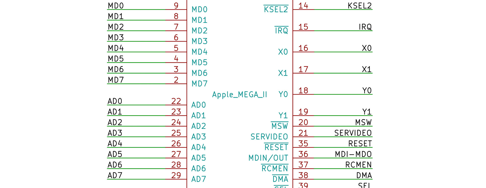
A project I work on in my spare time is creating a portable Apple II. Like many of my projects, one leads into another. I started out wanting to make a mobile Apple II, and now I’m working on a project called Bit Preserve. How did I get from one project to the next? Well, as I looked into how to make a portable Apple II, I realized a significant issue. The original Apple II logic board has almost 80 ICs. Being a design from 1975, they are all through-hole packages. The good news is that except for the ROM chips, they are all off-the-shelf components. But such a size means it might be impossible to turn it into something handheld. I almost abandoned the project. Then, I learned about a chip included in the Apple IIgs. The name of the ASIC is “MEGA II.” (Nothing to do with Arduino.) It is a chip that integrates all of those off-the-shelf chips into an 84 pin package.

As I dove deeper into the project, I realized I needed other support chips to make the MEGA II useful. There is a decent book that discusses the technical details of the Apple IIgs, but it does not get into chip or board level design. For that detail, I had to look at the original schematics. While I am ecstatic that someone archived these original documents as PDFs, I quickly became frustrated. Sometimes the scan quality is not very good, and it is nearly impossible to search for symbols across multiple pages. I thought to myself, “There has got to be a better way!”

Bit Preserve on GitHub
During a live stream, I was asked: “What is the Apple IIgs?” In this AddOhms Live Twitch Clip, I answer the question.

The Apple IIgs was the last of the highly successful Apple II line of computers. The “GS” stood for “graphics” and “sound.” Compared to previous Apple II computers, the IIgs was a fully 16-bit machine. When connected to its proprietary RGB monitor, it rendered a gorgeous display. Sadly, not much software took advantage of the improved graphics and sound capabilities. The IIgs was fully backward compatible with the older 8-bit line of Apple II computers. Its compatibility was so good that most IIgs users only used it in the compatibility mode.

How did the Apple IIgs achieve backward compatibility?

The IIgs contains an ASIC called the “MEGA-II.” (Which has nothing to do with the “Mega” Arduino boards.) It includes all of the individual logic chips from the original Apple II design as a single IC. Well, in addition to that IC you also need to add a CPU, RAM, and a ROM.

In my opinion, the Apple IIgs is best of the Apple IIs. In fact, of computers in that era, it is my overall favorite. When I got the IIgs, it replaced my previous pick: a Macintosh SE/30.

There is a project that has been sitting on my “to do” list for too long. My lab notebook has several dedicated pages for it. But I have not made progress. I decided to take some advice I have given to other people. When you’re stuck on starting a task, break down the project until you find a piece small enough you can get it done with no problem.

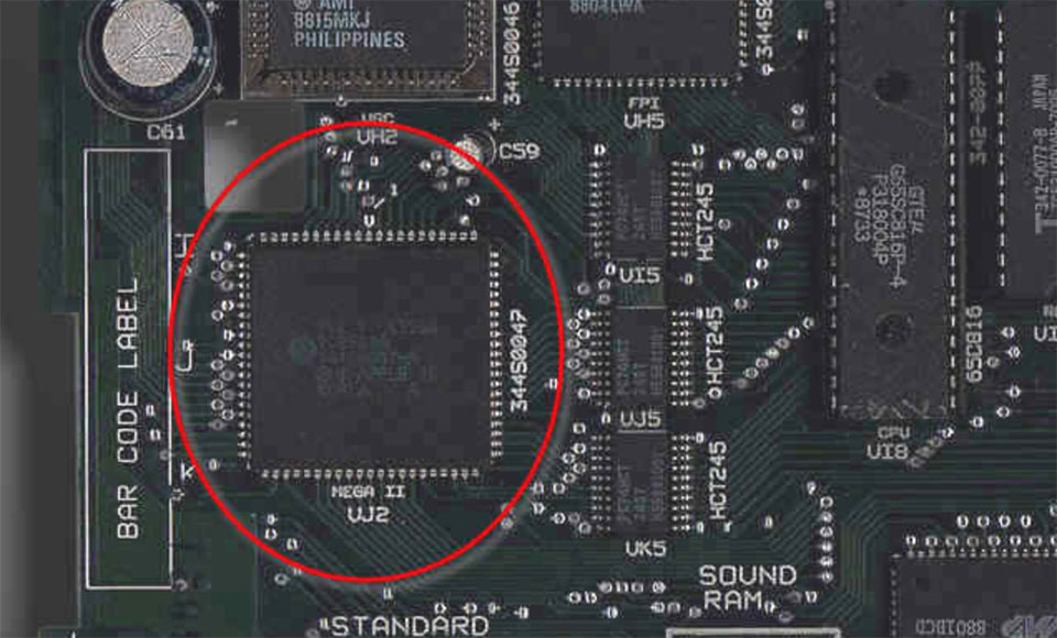
The project involves the Apple IIgs. It was Apple’s last 16-bit (and 8-bit) computer. Inside are some application specific integrated circuits or ASICs that make the IIgs. The name with my attention is named “MEGA-II.” It takes all of the individual logic chips from the original Apple II design and incorporates them into a single 84-pin PLCC.

MegaII from AppleLogic 960px
Image from Applelogic.org (Full)

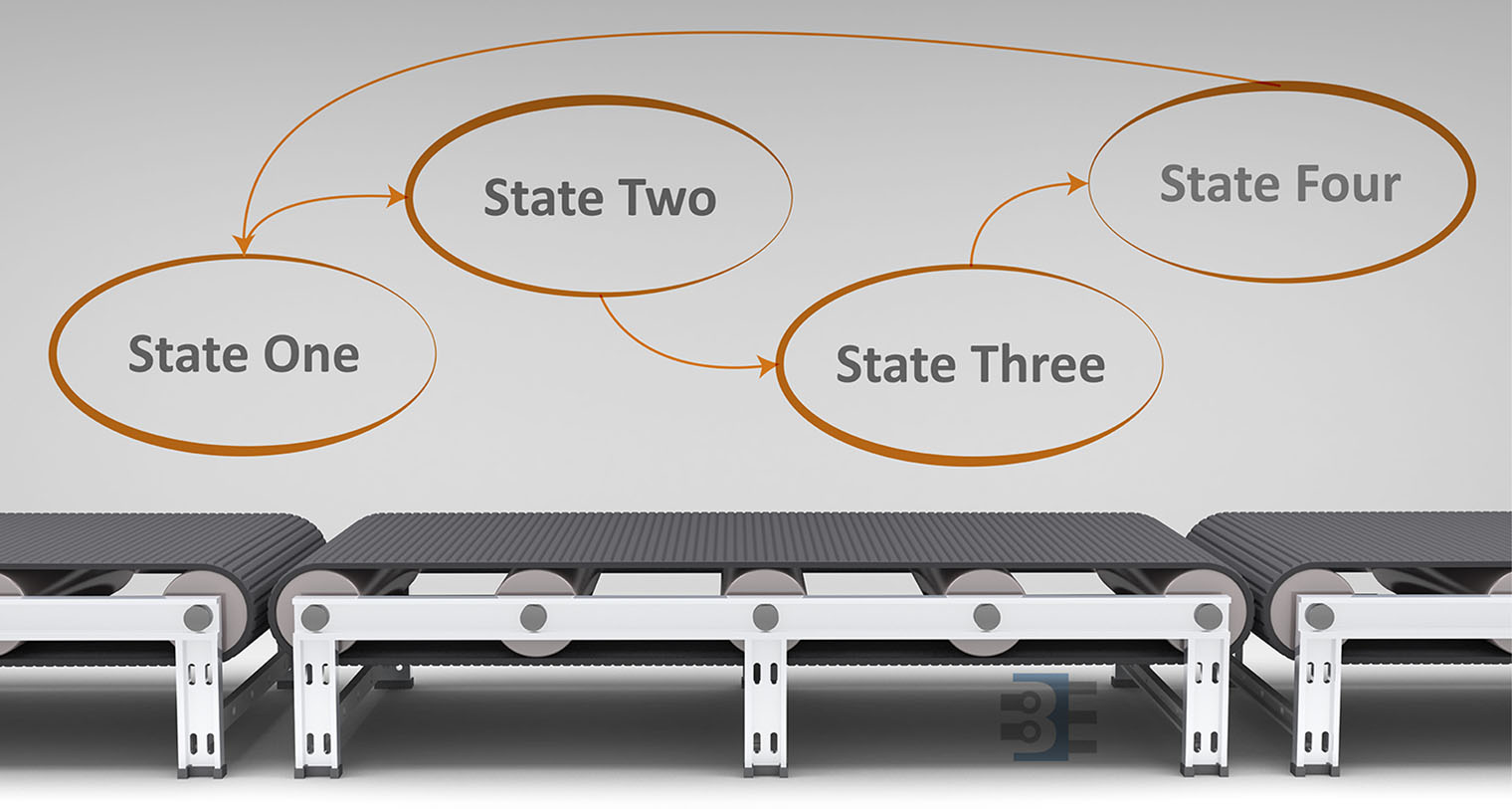
The last couple of weeks I have been making progress and posts on my RetroPie build. I’m putting a Raspberry Pi inside of an actual SNES (well Super Famicom). Part 1 covered the schematic for a Soft Power Controller. In Part 2 I broke down the RPSPC state machine. This 3rd and final post of the series is a Raspberry Pi startup script tutorial. It covers how to make scripts run at startup and shutdown.

When I started researching how to make Raspbian run a script at startup and shutdown, I found a ton of links and questions asking for help. None of them helpful. Why? Because they were wrong. At least, they are now.

/etc/rc.d doesn’t matter!

It turns out, Raspbian Jessie does not use SysV for init (anymore). So it does not matter what you scripts you put in /etc/rc.d. Pretty simple but missed by many!

Here is a correct Raspberry Pi Startup Script Tutorial.

The Key is systemd

Once I started researching how to make systemd do what I wanted, new problems emerged. The syntax for systemd is not as straightforward as I first thought. Thanks to readers, I was pointed towards the RedHat systemd manual. After reviewing it, I was able to create a service that runs at startup and shutdown.

In the end, I was unable to prevent this process from running during reboot. There seem to be some more layers to make sure systemd knows the difference. In the end, I decided it was not necessary to avoid the reboot.