
Before continuing with the state machine, first I need to thank all the mailing list members. You guys really rock. When I asked for state machine diagraming tool suggestions, you guys sent me enough options for an entire (future) post to compare them.
The Code
Here’s the code as of the time I write this article. I would recommend you check the GitHub repository for the latest. I won’t update this post as the code changes.
//retropie-pwr-cntrl-v4.ino
// This code expects a SPST slide switch
// For more information, visit baldengineer.com and search "SNES"

// Arduino Leonardo Pin Names
// Constants
const byte loadEnable = A1; // The Pi!
const byte offSignalPath = A3; //PF4 Verify: no additional Z, adc 4 on 32u4
const byte switchSense = A2;    //PF5
const byte signalToPi = A5;// PF0 (is HeartBeat on Pi)
const byte signalFromPi = 3;  //PD0 is SCL

const byte heartBeatLED = 6;
const byte frontLED = A4;       // PF1

// Extra Pins
const byte debugLED = 12;
const byte extraA1 = A1;  // PF6, Mine: A4 - Actually A1
const byte switchLED = A0; // PD6 (debug signal)

#define enableON HIGH
#define enableOFF LOW

// Timers
unsigned long previousOFFSignalCount = millis();
unsigned long previousOFFSignalInterval = 1000;

unsigned long heartBeatPreviousMillis = millis();
unsigned long heartBeatInterval = 500;
bool heartBeatState = true;

unsigned long timerOffPreviousMillis = millis();
unsigned long timerOffInterval = 15000;

unsigned long capDrainPreviousMillis = millis();
unsigned long capDrainInterval = 1000;

unsigned long forcePowerOff = millis();
unsigned long forcePowerOffInterval = 45000UL;
bool forcePowerOffState = false;

bool currentButtonState;
bool previousButtonState;

bool currentPiSignalState;
bool previousPiSignalState;

enum controllerStates {
	POWER_UP,
	BOOTING_PI,
	BOOTED,
	SHUT_DOWN_PI,
	POWER_DOWN
};
enum controllerStates controllerState = POWER_UP;
enum controllerStates previousControllerState = controllerState;

void setup() {
	Serial.begin(9600);	// debugging
	//pinMode(debugLED, OUTPUT);

	pinMode(offSignalPath, INPUT);

	pinMode(heartBeatLED, OUTPUT);
	pinMode(switchSense, INPUT);
	pinMode(signalFromPi, INPUT);

	// Don't want signal to go high until Pi has power
	pinMode(signalToPi, OUTPUT);
	digitalWrite(signalToPi, LOW);

	// Not ready to turn on the Pi yet
	pinMode(loadEnable, OUTPUT);
	digitalWrite(loadEnable, enableOFF);
}

void heartBeat(unsigned long millisTime) {
	if (millisTime - heartBeatPreviousMillis >= heartBeatInterval) {
		heartBeatState = !heartBeatState;
		digitalWrite(heartBeatLED, heartBeatState);
		heartBeatPreviousMillis = millisTime;
	}
}

void stateDebug() {
	if (previousControllerState != controllerState) {
		Serial.println(controllerState);
		previousControllerState = controllerState;
	}
}

void loop() {
	// blink the LED
	heartBeat(millis());

	// check where the Pi is at
	currentPiSignalState = digitalRead(signalFromPi);
	if (previousPiSignalState != currentPiSignalState) {
		// in case has some noise wait and re-sample
		delay(10);
		currentPiSignalState = digitalRead(signalFromPi);
		previousPiSignalState = currentPiSignalState;
	}

	// how is the button doing?
	currentButtonState = digitalRead(switchSense);
	if (previousButtonState != currentButtonState) {
		// in case of bounce, wait and re-sample
		delay(20);
		currentButtonState = digitalRead(switchSense);
		previousButtonState = currentButtonState;

		// let the Pi know if it should be on or off
		digitalWrite(signalToPi, currentButtonState);pi

		if (currentButtonState == LOW) {
			// user is forcing shutdown, so start emergency timer
			//timerOffPreviousMillis = millis();
			pinMode(offSignalPath, OUTPUT);
			digitalWrite(offSignalPath, HIGH);
			forcePowerOff = millis();
		} else {
			// Let the switch keep the cap charged
			pinMode(offSignalPath, INPUT);
		}
	}

	switch (controllerState) {
		case POWER_UP:
			stateDebug();
			// disable heart beat
			heartBeatPreviousMillis = millis();
			heartBeatState = false;

			// should be a no brainer.
			if (currentButtonState) {
				//pwrButtonState = SW_ON;
				controllerState = BOOTING_PI;
			}
		break;

		case BOOTING_PI:
			//stateDebug();
			heartBeatInterval = 1000;

			// Turn on the Pi
			digitalWrite(loadEnable, enableON);

			// wait for Pi to boot
			if (currentPiSignalState) {
				controllerState = BOOTED;
			}

			// kill the power if the Pi never boot (or we never)
			// get our PiAlive signal.
			if (currentButtonState == LOW) {
				capDrainPreviousMillis = millis();
				digitalWrite(signalToPi, LOW);
				controllerState = POWER_DOWN;
			}
		break;

		case BOOTED:
			//stateDebug();
			heartBeatInterval = 500;

			// wait for Pi signal that it is shutting down
			if (currentPiSignalState == LOW) {
				// Pi Initiated Shutdown
				timerOffPreviousMillis = millis();
				forcePowerOff = millis();
				controllerState = SHUT_DOWN_PI;
			}

			if (currentButtonState == LOW) {
				// User is telling Pi to shut down.
				timerOffPreviousMillis = millis(); // moved to switch change
				forcePowerOff = millis();
				controllerState = SHUT_DOWN_PI;
			} else {
				// let the swtich keep the cap up.
				pinMode(offSignalPath, INPUT);
			}
		break;

		case SHUT_DOWN_PI:
			//stateDebug();
			heartBeatInterval = 250;
			// give the Pi some time to finish up its power-down
			if (currentPiSignalState == LOW) {
				if (millis() - timerOffPreviousMillis >= timerOffInterval) {
					controllerState = POWER_DOWN;
					capDrainPreviousMillis = millis();
				}
			}

			// or a reboot is occured
			if (currentPiSignalState) {
				controllerState = BOOTED;
			}

			// Shutdown took way too long
			if (millis() - forcePowerOff >= forcePowerOffInterval) {
				controllerState = POWER_DOWN;
				capDrainPreviousMillis = millis();
			}
		break;

		case POWER_DOWN:
			//stateDebug();
			heartBeatInterval = 100;

			// let the cap drain once the switch goes off.
			if (currentButtonState == LOW) {
				// turn off the Pi
				digitalWrite(loadEnable, enableOFF);
				if (millis() - capDrainPreviousMillis >= capDrainInterval) {
					// drain the cap
					pinMode(offSignalPath, OUTPUT);
					digitalWrite(offSignalPath, LOW);
				}
			}
		break;
	}
}
The State Machine
It took me several sessions to get the state machine to work correctly. On the left is the original state machine I developed and on the right is the re-designed code.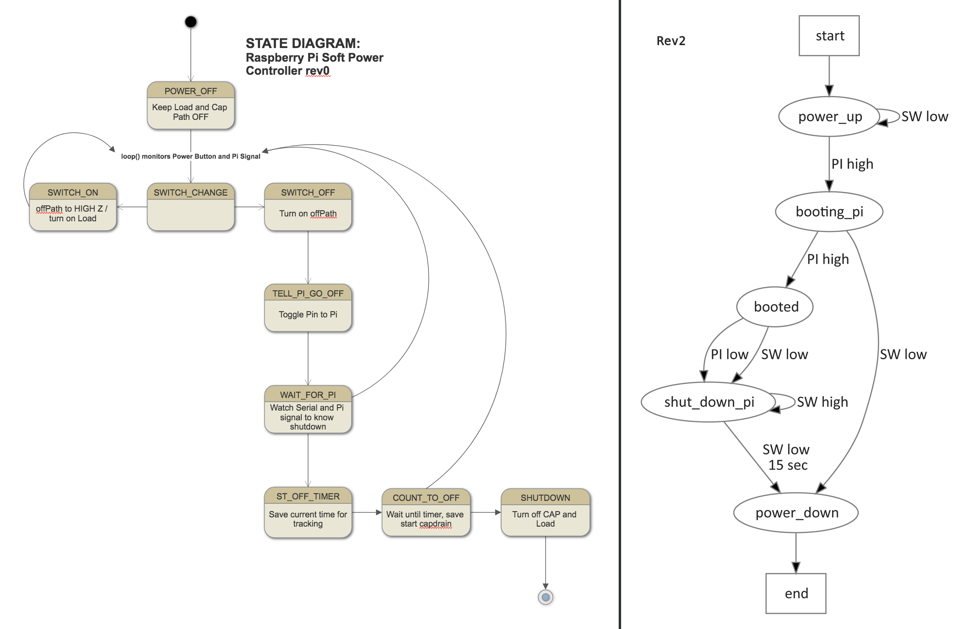 I asked the mailing list for suggestions on drawing a state diagram. I received many good suggestions, in fact, enough I plan a post on it. In the end, though, I ended up using “dot”, which is part of GraphViz.


2 Comments
Other background reading, with links to other similar projects here:- http://projects.descan.com/stuff/Project-iSwitchPi-en.pdf
Yeah, I found this originally when I started doing my research. I found the board to be ridiculously over-designed and complicated to use. But it has two positives: it is very flexible AND it only requires a single GPIO pin.