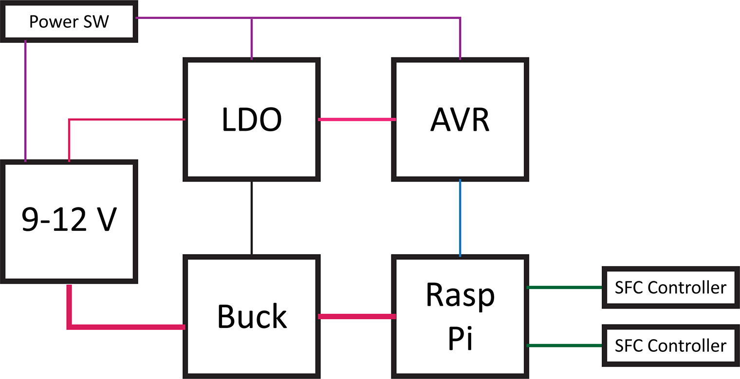
Category

Projects

Category

The RetroPie project enables retro-gaming with a Raspberry Pi. All of the Pi models have enough computing power to emulate the major 8-bit and 16-bit computers of the 80s and 90s. With the Pi 3 I have even been able to play PS1 games with no problem. My current project is to put my Raspberry Pi running RetroPie into an old Super Famicom (SFC), or SNES, case. The catch? I want the original SPST power switch to work. And by work, I mean allow the Raspberry Pi to shutdown properly when the switch goes into the off position.  To accomplish this task, I am building a Raspberry Pi soft power controller.

Raspberry Pi Soft Power Block Diagram

Here’s a block diagram of the power controller. The basic blocks in a Raspberry Pi soft power controller include the LDO, a switching supply for the Pi, an AVR-based microcontroller, and the Raspberry Pi. This post will describe each of these hardware blocks.

One design objective was to draw as little current as possible when off. For my RetroPie, I will not be running on battery. However, I do not like the idea of wasting energy when something is turned “OFF.”

This overview is a multi-post write-up. This first part is on the hardware. In the next post, I will explain the AVR’s firmware. Later, I will come back to the Raspberry Pi side of the project.

Last week’s post was on Project Sharing Sites. I’m using two for this project. Hackster.io will host the build log while GitHub has all of the design files. And by all of the file I mean the schematics, firmware, laser cutter files (soon), and Raspberry Pi code.

Hackster.io Project Page   GitHub Repo

DSLR Shoe AdapterWhen recording videos for either baldengineer.com or, more often, AddOhms, I need at least two things attached to my camera. I used a Canon T5i. The two devices I need to have connected are a shotgun microphone and a wireless receiver. In the past, I just let the remote’s wireless receiver dangle. That really bothered me.

I’m still surprised this DSLR shoe adapter didn’t already exist on Thingiverse. Anyway, I created one. Head over to Thingiverse to download it.

Last week I had a detailed Arduino tutorial on software pulse width modulation using millis() and micros(). Why? Because I wanted to create a Proper Larson Scanner, with persistence and at least 8 LEDs.

KITT larson scanner example
From Amazon

Even though it is a popular project for the Arduino Uno, most Larson scanner tutorials, like my first one, have a few flaws. First, there is no persistence, or tail, to the LED as it moves back and forth. Persistence could be solved by using pulse-width-modulation. The Uno and other 328p-based micros only have 6 Pulse Width Modulation (PWM) pins. And let’s be honest, every project is made better by adding more LEDs. 🙂

If you look at this cover shot of KITT from Knight Rider you will see there isn’t just a single light source. It appears multiple lights are turned on, as well as fading effect. This fading effect creates a tail. Of course, the reason is probably that standard light bulbs were being used back in the 80s. Traditional light bulbs don’t turn on or off nearly as fast as LEDs.

Presenting the Proper Larson Scanner

Knowing that a popular Halloween hack is to add Cylon (or KITT) lights to your pumpkins, I thought it was time for a Proper Larson Scanner. This code example does a couple of important things.

  1. It implements my “software pulse width modulation.”
  2. Can be used on all 20 I/O pins of an Uno (or other 328p Arduino)
  3. Does not use any delay()s!

So if you want to make your pumpkin even more Cylon-like this Halloween, check out this full tutorial on a proper Larson scanner.

The Arduino Uno has six pins dedicated to Pulse Width Modulation (PWM). PWM is great for analog-like control for the speed of motors or LED fading. But what if you want to control more than 6 devices? Or what if you’re using the PWM pins to control servo motors, but still want to fade an LED on a 7th pin?

One option is to change boards and processors. For example, you could move up to the Arduino Mega 2560. That means a bigger board and more cost.

Using millis() and micros(), it is possible to do PWM entirely in software. The best part is; if you can set the pin to OUTPUT, you can use this technique.

This tutorial will explain how you can use micros() and millis() to get more PWM pins on an Arduino Uno, Nano, or Pro Mini. It will probably work on other boards and processor types, but I haven’t tested them yet.

There’s a reason I needed this software PWM code. Subscribe to the mailing list, RSS feed, or follow me on social media to see why next week…

Apologies to the email subscribers if the code isn’t formatted correctly. Click here to read the full post.

NeoCorner from josh.com

If you’re working with the WS2812B and need to turn corners, you’ll want to check out this NeoPixel Corner adapter PCB from josh.com. It’s a pretty simple board. I came across it as a solution for an upcoming lighting project.

In josh’s example, he used a CNC to mill the PCBs. If you’re using one-sided FR4, that might work well. You’ll want to double-check thicknesses if you want to use OSHPark or similar.

You can check out the full write-up here or the NeoPixel Corner Board project GitHub.

On a related link, this document explains differences between WS2812 and WS2812B.