
The RetroPie project enables retro-gaming with a Raspberry Pi. All of the Pi models have enough computing power to emulate the major 8-bit and 16-bit computers of the 80s and 90s. With the Pi 3 I have even been able to play PS1 games with no problem. My current project is to put my Raspberry Pi running RetroPie into an old Super Famicom (SFC), or SNES, case. The catch? I want the original SPST power switch to work. And by work, I mean allow the Raspberry Pi to shutdown properly when the switch goes into the off position. To accomplish this task, I am building a Raspberry Pi soft power controller.
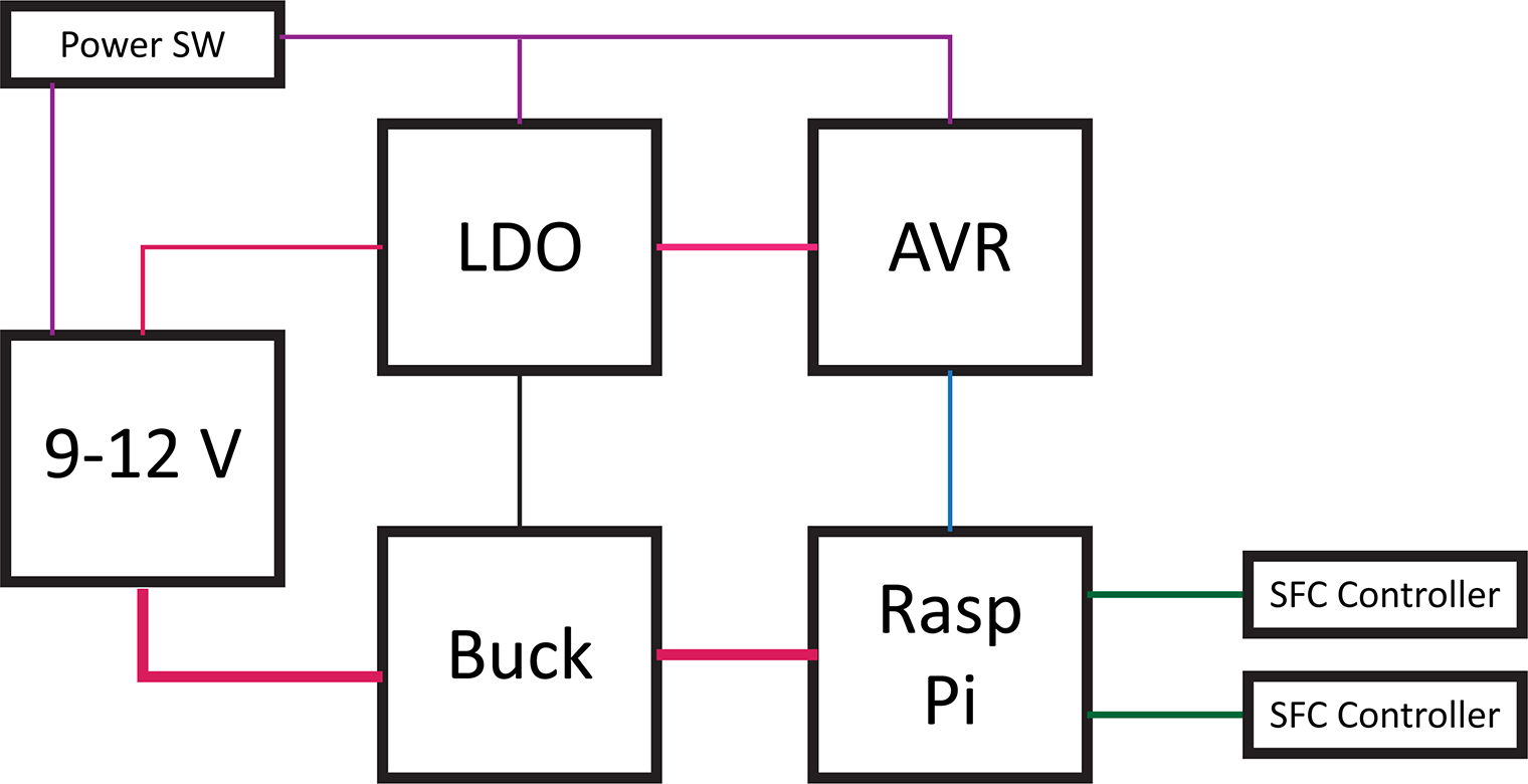
Here’s a block diagram of the power controller. The basic blocks in a Raspberry Pi soft power controller include the LDO, a switching supply for the Pi, an AVR-based microcontroller, and the Raspberry Pi. This post will describe each of these hardware blocks.
One design objective was to draw as little current as possible when off. For my RetroPie, I will not be running on battery. However, I do not like the idea of wasting energy when something is turned “OFF.”
This overview is a multi-post write-up. This first part is on the hardware. In the next post, I will explain the AVR’s firmware. Later, I will come back to the Raspberry Pi side of the project.
Last week’s post was on Project Sharing Sites. I’m using two for this project. Hackster.io will host the build log while GitHub has all of the design files. And by all of the file I mean the schematics, firmware, laser cutter files (soon), and Raspberry Pi code.
Hackster.io Project Page GitHub Repo
Raspberry Pi Soft Power Controller Switch
There is a slight twist when building a Raspberry Pi soft power controller using the SFC power switch. It is a sliding SPST and not a momentary push button. The circuit and state machine in the microcontroller do not change with either switch. I mention this point because if you plan to build your controller with a pushbutton, you may want to tweak the state machine a bit.
Discrete circuit
Initially, I tried building a latching supply based on an EEVBlog video. That design was for push buttons and is a clever circuit. However, the leakage currents when OFF were in the low milliamp range. When adding signals to sense the state of the switches, I started running into stability issues. Then a friend suggested an idea, why not use the ENABLE pin of an LDO? It already has a built-in load switch. Looking at specifications for LDOs, I found one from NJM that was rated for less than 100 nA when OFF. My measurements showed it was in the range of 10 nA.
With the LDO concept in place, it was time to design the rest of the Raspberry Pi soft power controller.
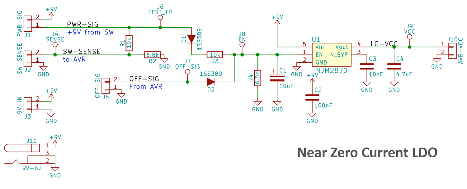
The LDO
The purpose of the LDO block is to provide power to the microcontroller. It only needs to manage about 15-20 mA of current.
The LDO I am using is an NJM2870. Its connections are straight forward. I used the data sheet’s recommended decoupling caps. With 9 V on the INPUT-pin and the EN-pin disabled, the circuit draws less than 10nA. I do not know the actual value because my multimeter was bouncing around. It stated a 0 A average (whatever that means).
For the input capacitor, I explicitly picked a high-quality C0G 100 nF. The reason is that C0G, like that from KEMET, is made with a Calcium Zirconate dielectric. This formulation is important because it results in an Insulation Resistance in the gigaohm range. In the switching supply section, I explain why that matters.
EN Hold-Up
A key to making this Raspberry Pi soft power controller work is putting a hold-up capacitor on the LDO’s EN-pin. In the schematic, I planned on using a 10 µF. In my final design, I used a 100 µF. I will explain the change in a minute. The idea is that when the power switch is transitioning from ON to OFF, the hold-up capacitor will keep the EN-pin active until the microcontroller can turn on an output and maintain the pin as active without the power switches.
Power Switch (or Button)
J1 on the schematic is the power switch. It connects the node PWR-SIG to +V. (In my case, 9 V). D1 (and D2) isolates the switch from the AVR signal, OFF-SIG. You might be wondering why there is a divider created by R3 and R4. My intention was not to create a voltage divider.
PWG-SIG to Enable
R3’s purpose is to limit the in-rush charging current of C1. R4 is there to limit the discharge rate of C1 when the EN node goes low. The result is a divider, apply about 3.7 V to EN. For the NJM2780 this is plenty since its threshold is 1.6 V. However, it means the cap will not get much charge. This reason is why I decided to change to 100 µF in my final design.
SW-SENSE
Related to PWR-SIG is SW-SENSE. For the microcontroller to manage its state machine, it needs to know the state of the power switch. Since I am using an AVR, the input voltage is limited to VCC. R1 and R2, intentionally, create a voltage divider to lower V+. This divider may fundamentally limit the minimum input voltage to 9 V. You may need a different divider here if you plan to operate the AVR at less than 5 volts.
OFF-SIG
IMHO, OFF-SIG is the magic of the entire Raspberry Pi soft power controller. When the microcontroller first powers up, this pin is in a high-impedance state. This state allows the PWR-SIG node to charge up the cap and enable the LDO. When SW-SENSE goes LOW, the microcontroller changes OFF-SIG to an OUTPUT and drives it HIGH. Based on my scope traces this process typically took less than 20 ms. (This is before any optimizations in my code.) The EN signal, at 9 V, took over 40 ms to reach the minimum rated “enable” voltage. Plenty of time for the microcontroller to take control of the EN signal.
OFF-SIG will stay high until the microcontroller receives a signal, or message, from the Raspberry Pi. That signal should occur during the shutdown process. At that point, the controller will give the Pi a pre-determined amount of time to finish any remaining tasks. Ideally, we will send the signal AFTER the Pi re-mounts the filesystem read-only. More on that coming soon.
After the Pi’s supply has been turned off, OFF-SIGNAL will drop LOW until C1 is completely discharged, disabling the LDO and turning off the microcontroller.
Microcontroller
Initially, I designed a complicated prototype board where 2 of the 3 blocks on the board did not work. The one block that did work was the 32u4 based controller. It manages the power controller sequence and is driven by the LDO. My RetroPie build will also accept inputs from SNES controllers. So the Raspberry Pi soft power controller will also include some I/O pins for SNES controllers. I am re-using the controller ports on the front of the SFC case!
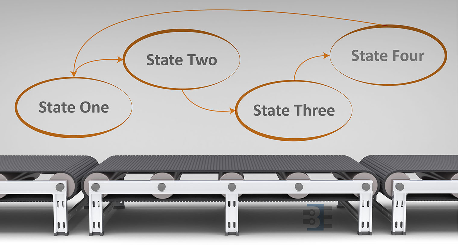
In the next post, I am going to walk through its state machine. For now, you can visit the Raspberry Pi soft power controller GitHub page to see the code.
Switching Regulator
The switching regulator is based on a TPS563200. The design is a basic buck converter. To be honest, I did not do much “design.” I used TI’s WEBENCH tool. The tool lets you input your parameters, select what is important, and then provides a suggested circuit.
From there, I designed a PCB based on their recommended layout. The only change I made was to cross TI’s suggested components to KEMET equivalents, for obvious reasons. If you have not used WEBENCH yet, you owe it to yourself to try on your design power supply design.
Zero Current Got Less 0
At this point, I connected all the blocks together. After a few test runs, the prototype Raspberry Pi soft power controller worked. I pushed a button (simulating my slide switch) which turned on the AVR and enabled the Pi. From the Pi, I could toggle a GPIO causing the Pi’s supply to shut down and then the AVR to turn itself off.
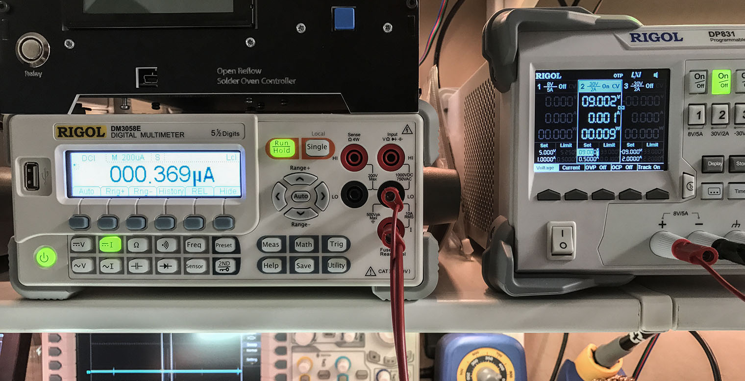
However. I noticed that in “stand-by” or “OFF,” my supply was now drawing 350 nA. (In fact, at 12 V it draws about 850 nA.) What is drawing all that current? Being that I (currently) work at a capacitor company, I always seem to blame the capacitors. This time, I was right.
Big Input Capacitor
The switching circuit has a 10 µF ceramic input capacitor. The thing is, with high capacitance X5R parts, they have a low insulation resistance. Now low in this case means 10 MΩ. This value is a limit; the actual value is going to be slightly higher.) Compared the C0G 100 nF I used on the LDO; this value is orders of magnitude lower. Quick ohm’s law says that nominally at 9 V, the leakage current of this capacitor is 900 nA.
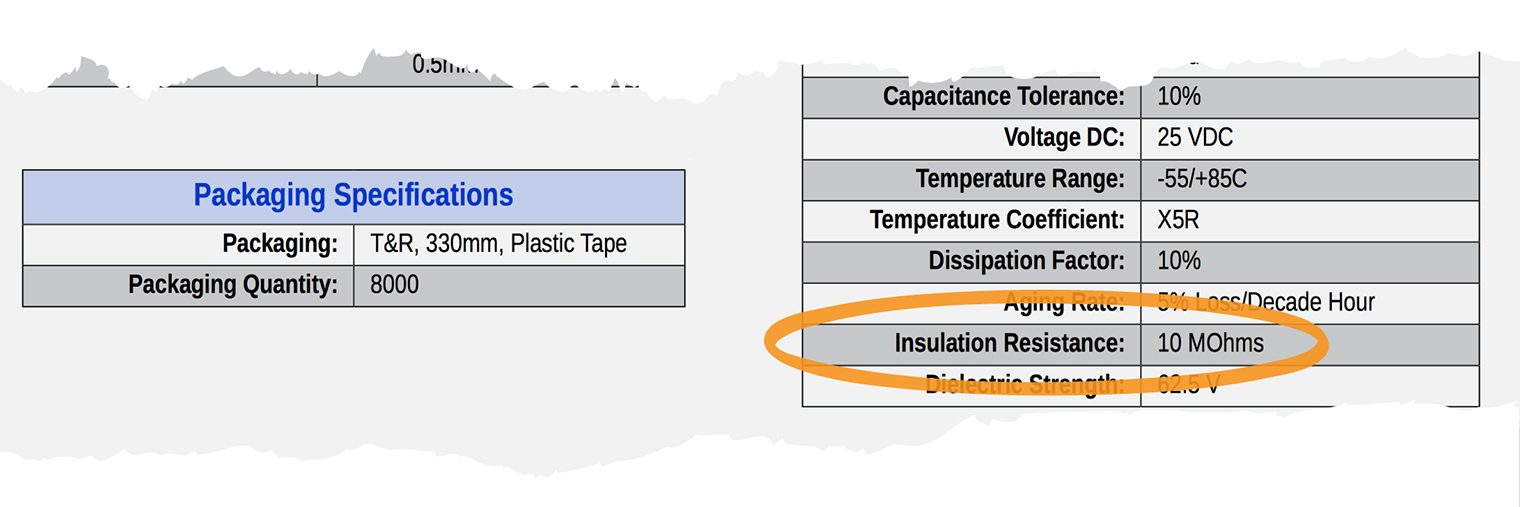
Doesn’t take much to realize the majority of that 300 nA value I see now is probably that 10 µF cap. One option could be using a FET to disable the switching regulator’s input. Since my circuit is not using a battery power, I am not going to try changing it now. However, I can see that being a future experiment.
Conclusion
This circuit provides an elegant Raspberry Pi soft power controller. There are a few trade-offs which a later revision could address:
1) It requires >5 V to operate. This decision was because I wanted to use an off-the-shelf wall-wart to power the RetroPie. 9- and 12-volt supplies are more common. Also, they are pretty cheap compared to a 5V/3A rated supply.
2) While my circuit does an excellent job of saving power, the off-the-shelf wall-wart may not. Oh well.
3) Version 1 of the LDO circuit on the GitHub project has a flaw with the barrel jack. Be careful if you have this board fabbed. The switching supply board is missing mounting holes. And Version 1 of the Retropie controller is junk. :/
4) There’s probably better ways to do all of this, which I am sure you will let me know in the comments.
Next Steps
Next week I will post details on the microcontroller code. The state machine is working but does still have a few bugs. There are also several features I still want to implement. The GitHub project has all of the code if you want to help.
Here’s where I could use some help. Debian Linux does not use the /etc/rcX.d scripts. Even though every StackOverflow question says that is where to put startup and shutdown code, they are wrong. Debian Linux, which is what Raspbian and RetroPie use, is using systemd.
I am having a hell of a time figuring out how to run a small program on startup and shutdown, but not reboot. Can anyone help finish the Raspberry Pi soft power controller (and part 3 of this tutorial… *grin*)?


11 Comments
I had to address power management in my raspberry pi car-pc project. Here’s what I came up with:
https://www.comvette.com/blog_2017-01-27.php
I wanted to build the solution with of the shelf parts. So far it has worked really well.
That’s a nice clean build. Great job.
I think this is a neat project; i will be following along and know i am in for some learning.
I am new to Pi, so many things are still frustrating at this point.
Bob D
Even better example that will run “runonstart.sh” on startup (this file is called “runonstart.service”)…
—
[Unit]
Description=Run on startup
#After=network.target
[Service]
ExecStart=/usr/local/bin/runonstart.sh
Type=forking
#Restart=on-abort
#User=pi
[Install]
WantedBy=multi-user.target
—
And a script to safely install the above service….
—
#copy script to a univeral location so it will always be in the same place…
cp runonstart.sh /usr/local/bin/
#Stop any running instances to clear access to the files
sudo systemctl stop runonstart.service
#copy the service unit files to the right place
sudo cp runonstart.service $(pkg-config systemd –variable=systemdsystemunitdir)
#force a reload in case we are overwriting existing files with new versions
sudo systemctl daemon-reload
#set the service to run on boot
sudo systemctl enable runonstart.service
#…and start it now so we don’t have to wait until next reboot
sudo systemctl start runonstart.service
—
LMK if any questions!
-josh
Here is a simple example of a “service” that will run a script on startup using the systemd stuff…
https://github.com/bigjosh/De-Harak-Clock-Controller/blob/master/ledsd.service
..and here is a little script that will install (and manually start the first time) the above service into the system..
https://github.com/bigjosh/De-Harak-Clock-Controller/blob/master/install-service.sh
Not hard, but lots of ceremony.
LMK if any questions!
-josh
is this suitable for RPi3, too, which is adviced to power with a 5V-3A PSU? Thanks
I designed my switching supply to provide ~3A, this was based on the Pi’s website suggestion of a 2.5A supply. I didn’t have a board available to measure, so I couldn’t verify the current draw with WiFi and BT enabled. Plus I wanted to support up to 4 game controllers drawing less than 100mA each.
If my supply design doesn’t provide your circuit enough current, you could replace it. Provided, it has an ENABLE.
this can help?
https://unix.stackexchange.com/questions/284598/systemd-how-to-execute-script-at-shutdown-only-not-at-reboot
That was the question I found which helped me realized Jessie was using systemd and not sysvinit. However, I haven’t found a good explanation of how to configure systemd services. (Or really, I haven’t spent enough time learning about systemd’s configurations yet.) I’ve copied and pasted every answer I could find, but can’t get to the behavior I want. I want to run a certain program on boot. Then on shutdown I want to run a certain program after the filesystem has been remounted RO. However, I do not want the “shutdown” program to run if the condition is reboot.
All of the stack overflow questions follow the same kind of pattern. Person asks the question I am asking. They or someone else posts a potential solution, but can’t explain why it works for them. Others cannot make it work. Or someone posts a solution with “something like this…” but then all of the comments say it doesn’t work.
the clearest guide i can find to systemd management is the RedHat one…
https://access.redhat.com/documentation/en-US/Red_Hat_Enterprise_Linux/7/html/System_Administrators_Guide/chap-Managing_Services_with_systemd.html#sect-Managing_Services_with_systemd-Introduction
in particular the 9.3 section describes the target, the one you’re looking for is poweroff.target, as stated by my previous comment:
https://access.redhat.com/documentation/en-US/Red_Hat_Enterprise_Linux/7/html/System_Administrators_Guide/sect-Managing_Services_with_systemd-Targets.html
Thank you! Much better than the guides I found. Let me dig in using this. Thanks.