The Apple II’s CPU clock has jitter or a glitch. This issue is not new—it has been present since its original design in 1977! Bald Engineer uses an oscilloscope to show how often the glitch occurs and how to correlate that jitter to its source—which is useful when you are not testing 40-year-old devices. The device under test (DUT) in this video is the Mega IIe project. It’s a fully compatible Apple IIe built around the Mega II chip.
These links accompany the Mega IIe presentation at Supercon 2023.
Out of context screenshots are out of context
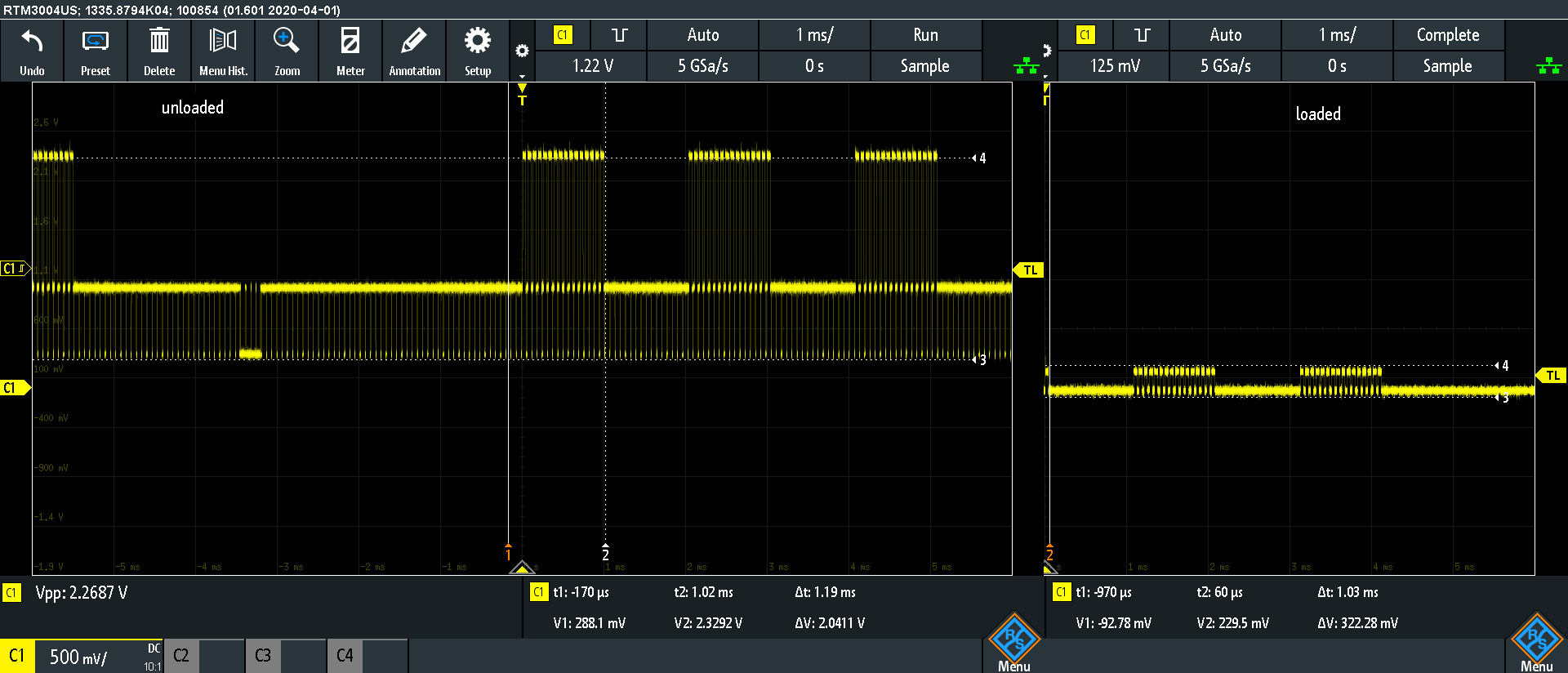
On the Mini Apple IIe project, I am testing the composite/sync amplifier, which is an MC1377. The composite output looks great, until connecting the output cable to a receiver. It outputs about 2.6 Vpp until loaded with 75 ohms, then it drops to about 400 mVpp. We have replaced most of the passives on the output and have tried 3 different MC1377s. The measurements below are from a known good MC1377 removed from a working Apple IIgs.
Here is an MC1377 datasheet mirror link. The Figure references below match Page 8 of that datasheet. The biggest suspects are the Luma signals.
Not captured, but tested, none of the input signals change amplitude when the output (pin 9) is loaded with a 75 ohm load.
Problem: Update, SOLVED
These two screenshots are the same point, RCA Out Header in the schematic. On the left is the output when the node is left open. It is about 2.6Vpp with minimal DC offset. However, when the signal is terminated with a 75 ohm resistor (or a receiver circuit) it drops to about 300 mVpp!
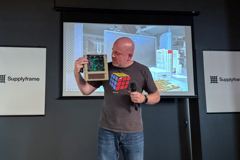
A project I work on in my spare time is creating a portable Apple II. Like many of my projects, one leads into another. I started out wanting to make a mobile Apple II, and now I’m working on a project called Bit Preserve. How did I get from one project to the next? Well, as I looked into how to make a portable Apple II, I realized a significant issue. The original Apple II logic board has almost 80 ICs. Being a design from 1975, they are all through-hole packages. The good news is that except for the ROM chips, they are all off-the-shelf components. But such a size means it might be impossible to turn it into something handheld. I almost abandoned the project. Then, I learned about a chip included in the Apple IIgs. The name of the ASIC is “MEGA II.” (Nothing to do with Arduino.) It is a chip that integrates all of those off-the-shelf chips into an 84 pin package.
As I dove deeper into the project, I realized I needed other support chips to make the MEGA II useful. There is a decent book that discusses the technical details of the Apple IIgs, but it does not get into chip or board level design. For that detail, I had to look at the original schematics. While I am ecstatic that someone archived these original documents as PDFs, I quickly became frustrated. Sometimes the scan quality is not very good, and it is nearly impossible to search for symbols across multiple pages. I thought to myself, “There has got to be a better way!”
During a live stream, I was asked: “What is the Apple IIgs?” In this AddOhms Live Twitch Clip, I answer the question.
The Apple IIgs was the last of the highly successful Apple II line of computers. The “GS” stood for “graphics” and “sound.” Compared to previous Apple II computers, the IIgs was a fully 16-bit machine. When connected to its proprietary RGB monitor, it rendered a gorgeous display. Sadly, not much software took advantage of the improved graphics and sound capabilities. The IIgs was fully backward compatible with the older 8-bit line of Apple II computers. Its compatibility was so good that most IIgs users only used it in the compatibility mode.
How did the Apple IIgs achieve backward compatibility?
The IIgs contains an ASIC called the “MEGA-II.” (Which has nothing to do with the “Mega” Arduino boards.) It includes all of the individual logic chips from the original Apple II design as a single IC. Well, in addition to that IC you also need to add a CPU, RAM, and a ROM.
In my opinion, the Apple IIgs is best of the Apple IIs. In fact, of computers in that era, it is my overall favorite. When I got the IIgs, it replaced my previous pick: a Macintosh SE/30.


