Active components like transistors, BJTs, MOSFETs, and integrated circuits (ICs) make it possible to control circuits. This video explains the must-have NPN and PNP BJTs. For MOSFETs there are a couple of N-Channels and P-Channels to consider. Basic ICs include some digital logic stuff from the 7400-family as well as the venerable 555-timer to have on-hand. We did not forget Op-Amps either. Spoiler: We do not recommend the ua741!
Turning on a MOSFET takes more than knowing the threshold voltage. A special event occurs when a FET turns on, which is called the Miller Plateau. The gate voltage sticks to the threshold voltage while the drain opens up. In this video, James shows how to measure the Miller Capacitance, using an oscilloscope and custom MOSFET test board.
This video came from some measurements I did on a live stream. I had intended to demonstrate something else, but the board I created was such a great demo board for the Miller Effect.
When it comes to transistors, there are only so many things a multimeter can measure. The DCA Pro from PEAK Electronics makes short work of testing parts like a transistor. This small device can determine pinout, component type, and essential parameters in a matter of seconds. Not only that but it can be connected to a (Windows) PC and draw parameter curves.
Check out the video review to see how the device and software work. Then head over to the element14 page where you can download a zip file full of example parts I measured for you. Use the free DCA Pro software to open them.
You might also want to check out this MOSFET Curves post, which complements this video tutorial. Another resource you might find helpful on semiconductors, or transistors, is this post on MOSFET Myths.
See more on element14
The most popular AddOhms video is my short tutorial on MOSFET basics. In the years since I posted the video, people have sent me many questions. While answering those questions I’ve learned quite a bit as well. For example, in that video, I say that Vgs is the threshold to turn on the MOSFET. Well, it turns out, that is not entirely true. It is the threshold to turn it off! Oops. A minor point with a subtle difference, but a common MOSFET misconception.
In this post, I dispel that and other common myths and misconceptions around using MOSFETs. As with all engineering tips and tricks, this post is not a definitive guide to FETs. Instead, it is meant to be a guide to help you ask the right questions to design in the correct part.
1. Misconception: You don’t need resistors on the gate
Back when I made the AddOhms episode, I added a resistor to the MOSFET’s gate pin. Of course any time a resistor is shown in a schematic, people get worried about what complicated formula is needed to determine its value. For slow switching applications, like below 10 kHz, the resistor value doesn’t matter. Something in the 100 to 1000 ohm range is fine.
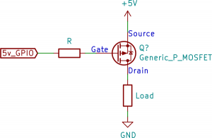
So if the value does not matter, why have one? The gate of a MOSFET is a small capacitor. And what happens when applying a voltage to a capacitor? It starts charging.
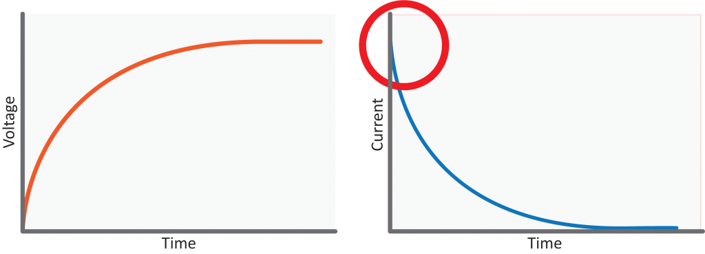
The initial current is very high. It slows down as the capacitor charges. That initial current rush, also known as in-rush current, can be a problem. Even though it is a short time, there is a significant current surge that can damage an I/O pin. Depending on the size of the MOSFET’s gate capacitance, it may not be necessary to include that resistor. I wish I could say to “just” add it any time you use a MOSFET. If there is a high switching frequency, say 100 kHz or higher, then you have to worry about the RC charging curve created by the resistor and the gate capacitance.

A common task for a transistor is switching a device on and off. There are two configurations for a transistor switch: low side and high side. The location of the transistor determines the type of circuit and its name. Either transistor configuration can use a BJT or MOSFET.
In this post, I draw the configuration for both transistor types, discuss which requires a driver, and explain why you would use either. If you are new to transistors, check out the resource links at the bottom. I have a few videos I made and some from element14’s The Learning Circuit, which do a great job introducing transistors.