Tag

led

Browsing

When it comes to transistors, there are only so many things a multimeter can measure. The DCA Pro from PEAK Electronics makes short work of testing parts like a transistor. This small device can determine pinout, component type, and essential parameters in a matter of seconds. Not only that but it can be connected to a (Windows) PC and draw parameter curves. Check out the video review to see how the device and software work.…

Last week I had a detailed Arduino tutorial on software pulse width modulation using millis() and micros(). Why? Because I wanted to create a Proper Larson Scanner, with persistence and at least 8 LEDs.

KITT larson scanner example
From Amazon

Even though it is a popular project for the Arduino Uno, most Larson scanner tutorials, like my first one, have a few flaws. First, there is no persistence, or tail, to the LED as it moves back and forth. Persistence could be solved by using pulse-width-modulation. The Uno and other 328p-based micros only have 6 Pulse Width Modulation (PWM) pins. And let’s be honest, every project is made better by adding more LEDs. 🙂

If you look at this cover shot of KITT from Knight Rider you will see there isn’t just a single light source. It appears multiple lights are turned on, as well as fading effect. This fading effect creates a tail. Of course, the reason is probably that standard light bulbs were being used back in the 80s. Traditional light bulbs don’t turn on or off nearly as fast as LEDs.

Presenting the Proper Larson Scanner

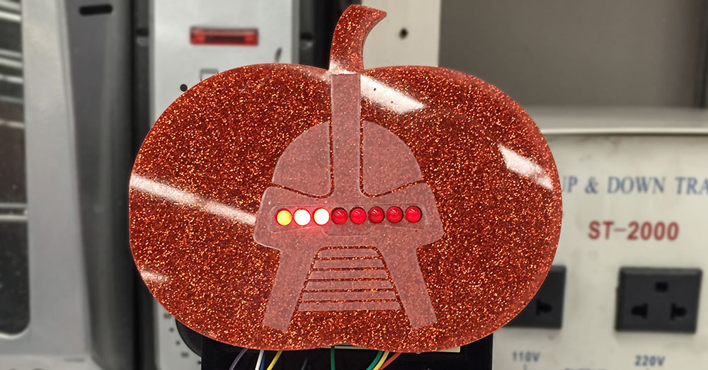
Knowing that a popular Halloween hack is to add Cylon (or KITT) lights to your pumpkins, I thought it was time for a Proper Larson Scanner. This code example does a couple of important things.

  1. It implements my “software pulse width modulation.”
  2. Can be used on all 20 I/O pins of an Uno (or other 328p Arduino)
  3. Does not use any delay()s!

So if you want to make your pumpkin even more Cylon-like this Halloween, check out this full tutorial on a proper Larson scanner.

The Arduino Uno has six pins dedicated to Pulse Width Modulation (PWM). PWM is great for analog-like control for the speed of motors or LED fading. But what if you want to control more than 6 devices? Or what if you’re using the PWM pins to control servo motors, but still want to fade an LED on a 7th pin?

One option is to change boards and processors. For example, you could move up to the Arduino Mega 2560. That means a bigger board and more cost.

Using millis() and micros(), it is possible to do PWM entirely in software. The best part is; if you can set the pin to OUTPUT, you can use this technique.

This tutorial will explain how you can use micros() and millis() to get more PWM pins on an Arduino Uno, Nano, or Pro Mini. It will probably work on other boards and processor types, but I haven’t tested them yet.

There’s a reason I needed this software PWM code. Subscribe to the mailing list, RSS feed, or follow me on social media to see why next week…

Apologies to the email subscribers if the code isn’t formatted correctly. Click here to read the full post.

How to blink (or flash) a LED without delay() and detect button pushes

One of the limitations of the delay() function is that nothing else can really be done. This presents a problem when you want to flash a LED while waiting for a pushbutton to be pressed.

Flashing the LED with millis() and using a flag variable to find if the LED should be flashing solves this problem.

Consider this another example to my virtual millis() cookbook.

This code (below) should work with both Arduino (AVR) and Energia (supported boards), but to be honest, I haven’t had a chance to test it on my MSP430 yet.

A popular LED project is the “Larson Scanner.” This scanner emulates the effect seen on KIT from Knight Rider and the Cylons in Battlestar Galactica. The code is usually written using “delay()” which means you can’t combine it with anything else. The following code could be put into a function, called periodically and allow your code to scan while doing other things.