")
The Arduino Uno has six pins dedicated to Pulse Width Modulation (PWM). PWM is great for analog-like control for the speed of motors or LED fading. But what if you want to control more than 6 devices? Or what if you’re using the PWM pins to control servo motors, but still want to fade an LED on a 7th pin?
One option is to change boards and processors. For example, you could move up to the Arduino Mega 2560. That means a bigger board and more cost.
Using millis() and micros(), it is possible to do PWM entirely in software. The best part is; if you can set the pin to OUTPUT, you can use this technique.
This tutorial will explain how you can use micros() and millis() to get more PWM pins on an Arduino Uno, Nano, or Pro Mini. It will probably work on other boards and processor types, but I haven’t tested them yet.
There’s a reason I needed this software PWM code. Subscribe to the mailing list, RSS feed, or follow me on social media to see why next week…
Apologies to the email subscribers if the code isn’t formatted correctly. Click here to read the full post.
Software PWM Code
Here’s the full code for my PWM example. In this example, I am fading half of the pins at one rate and the other half at another. Really, you could treat this to any pattern you already have, I just did this to test how fast the code ran.
You can also download this software PWM code from my pastebin.
//pwm-with-millis.ino

// macros for LED state
#define ON true
#define OFF false

// variables for pattern timing
unsigned long currentMillis = millis();
unsigned long previousMillis = 0;
unsigned long millisInterval = 100;

// variables for software PWM
unsigned long currentMicros = micros();
unsigned long previousMicros = 0;
// this is the frequency of the sw PWM
// frequency = 1/(2 * microInterval)
unsigned long microInterval = 250;

const byte pwmMax = 100;

// fading (for the timing)
int fadeIncrement = 1;

// typedef for properties of each sw pwm pin
typedef struct pwmPins {
  int pin;
  int pwmValue;
  bool pinState;
  int pwmTickCount;
} pwmPin;

// create the sw pwm pins
// these can be any I/O pin
// that can be set to output!
const int pinCount = 8;
const byte pins[pinCount] = {2,3,5,6,9,10,11,12};

pwmPin myPWMpins[pinCount];

// function to "setup" the sw pwm pin states
// modify to suit your needs
// this creates an alternating fade pattern
void setupPWMpins() {
  for (int index=0; index < pinCount; index++) {
    myPWMpins[index].pin = pins[index];

    // mix it up a little bit
    // changes the starting pwmValue for odd and even
    if (index % 2)
      myPWMpins[index].pwmValue = 25;
    else
      myPWMpins[index].pwmValue = 75;

    myPWMpins[index].pinState = ON;
    myPWMpins[index].pwmTickCount = 0;

    // unlike analogWrite(), this is necessary
    pinMode(pins[index], OUTPUT);
  }
}

void pwmFadePattern() {
  // go through each sw pwm pin, and increase
  // the pwm value. this would be like
  // calling analogWrite() on each hw pwm pin
  for (int index=0; index < pinCount; index++) {
    myPWMpins[index].pwmValue += fadeIncrement;
    if (myPWMpins[index].pwmValue > 100)
      myPWMpins[index].pwmValue = 0;
  }
}

void handlePWM() {
  currentMicros = micros();
  // check to see if we need to increment our PWM counters yet
    if (currentMicros - previousMicros >= microInterval) {
    // Increment each pin's counter
    for (int index=0; index < pinCount; index++) {
    // each pin has its own tickCounter
      myPWMpins[index].pwmTickCount++;

    // determine if we're counting on or off time
      if (myPWMpins[index].pinState == ON) {
        // see if we hit the desired on percentage
        // not as precise as 255 or 1024, but easier to do math
        if (myPWMpins[index].pwmTickCount >= myPWMpins[index].pwmValue) {
          myPWMpins[index].pinState = OFF;
        }
      } else {
        // if it isn't on, it is off
        if (myPWMpins[index].pwmTickCount >= pwmMax) {
          myPWMpins[index].pinState = ON;
          myPWMpins[index].pwmTickCount = 0;
        }
      }
      // could probably use some bitwise optimization here, digitalWrite()
      // really slows things down after 10 pins.
      digitalWrite(myPWMpins[index].pin, myPWMpins[index].pinState);
    }
    // reset the micros() tick counter.
    digitalWrite(13, !digitalRead(13));
    previousMicros = currentMicros;
  }
}

void setup() {
  setupPWMpins();
  pinMode(13, OUTPUT);
}

void loop() {
  // this is the magic for sw pwm
  // need to call this anytime you
  // have a long operation
  handlePWM();

  // check timer for fading pattern
  // this would be the same
  // if we used analogWrite()
  currentMillis = millis();
  if (currentMillis - previousMillis >= millisInterval) {
    // moved to own funciton for clarity
    pwmFadePattern();

    // setup clock for next tick
    previousMillis = currentMillis;
  }
}

// Code from [email protected]
// email | twitter | www
// See more at: https://www.baldengineer.com/software-pwm-with-millis.html
How to use Software PWM Code
Right now the code isn’t a library, so it is made to be easily integrated into your code. I’ve provided section-by-section comments, but here are the key things you need to know.
millis() timing code
There’s nothing special about the millis() timing code used here. I’ve set it up to slowly fade the LEDs up. For more information on millis() checkout my millis() Cookbook examples. You might also want to read my blinkWithoutDelay Line-by-Line Tutorial.
Basic millis() variable setup
If you want to change the speed of the fade, modify millisInterval.
pwmFadePattern() (For Example Only)
Again, this is just my example code of how to handle the software PWM code. This for-loop() is just going through my software PWM pins and incrementing their fade value. This would replace an analogWrite() if you were using the hardware pins.
Software PWM
These sections of code are critical to using the software PWM code. In other words, these are the parts you want to copy and paste!
Setup PWM Timing Variables
For SW PWM, I’m using micros(). My testing showed that millis() didn’t have enough resolution. micros(), on the other hand, is slightly less stable if you pick as small interval value.
// line 12
// variables for software PWM
unsigned long currentMicros = micros();
unsigned long previousMicros = 0;
// this is the frequency of the sw PWM
// frequency = 1/(2 * microInterval)
unsigned long microInterval = 250;

const byte pwmMax = 100;
The variable microInterval sets the frequency of the PWM. See my note in the conclusion about measuring and changing this frequency.
For a maximum value and resolution, I picked 100. I thought it was easier to do the math with a decade value, so pwmMax is adjustable. I haven’t tried yet, but assume you could get more “bits” of resolution by making it bigger. In my current example the LEDs aren’t quite as smooth as I like, but for my bigger project that might be okay.
Creating a typedef for pin descriptions
Since the pins need multiple attributes, I decided to create a typedef. This lets me easily create an array of “pins” that have multiple variables assigned to them.
// line 25
typedef struct pwmPins {
   int pin;
   int pwmValue;
   bool pinState;
   int pwmTickCount;
} pwmPin;
The names of the variables were picked on purpose. They are the pin number, the desired “on” time for the PWM, whether the pin is on or off, and a timer-tick value.
pwmTickCount allows us to track when it is time to turn the pin back off. In the back of my mind, I keep thinking each pin doesn’t need its own ticker. Maybe a future improvement.
Create an Array of Pins
This array defines the pin numbers we want to use and the number of pins. pinCount is used throughout the code. The pins[] array, however, is only used to set up the actual PWMpins.
// line 35
const int pinCount = 8;
const byte pins[pinCount] = {2,3,5,6,9,10,11,12};
Now we create an array of our typedefs.
// line 38
pwmPin myPWMpins[pinCount];
From this point forward, whenever you want to change one of the software PWM pins, refer to *THIS* array.
Setup SW PWM Pins
This code is necessary but can be modified for your needs. In this example, I am preloading every other LED with either a small or large number. This will create a pattern when I loop through the PWM values.
// line 43
void setupPWMpins() {
   for (int index=0; index < pinCount; index++) {
      myPWMpins[index].pin = pins[index];

      // mix it up a little bit
      // changes the starting pwmValue for odd and even
      if (index % 2)
         myPWMpins[index].pwmValue = 25;
      else
         myPWMpins[index].pwmValue = 75;

      myPWMpins[index].pinState = ON;
      myPWMpins[index].pwmTickCount = 0;

      // unlike analogWrite(), this is necessary
      pinMode(pins[index], OUTPUT);
   }
}
Notice how the for()-loop grabs the pin number from the pins[] array and assigns it to a pin in the myPWMpins array.
The big show: handlePWM()
Inside of loop(), I am calling this function, handlePWM(). Anytime you have a long stretch of code, you should call handlePWM(). If it isn’t time to do anything, the function will simply exit.
The idea is that you want to keep “pinging” this function, to see if it is time to do anything with the PWM pins.
// line 73
void handlePWM() {
   currentMicros = micros();
   // check to see if we need to increment our PWM counters yet
   if (currentMicros - previousMicros >= microInterval) {
      // Increment each pin's counter
      for (int index=0; index < pinCount; index++) {
         // each pin has its own tickCounter
         myPWMpins[index].pwmTickCount++;

         // determine if we're counting on or off time
         if (myPWMpins[index].pinState == ON) {
            // see if we hit the desired on percentage
            // not as precise as 255 or 1024, but easier to do math
            if (myPWMpins[index].pwmTickCount >= myPWMpins[index].pwmValue) {
              myPWMpins[index].pinState = OFF;
            }
         } else {
            // if it isn't on, it is off
            if (myPWMpins[index].pwmTickCount >= pwmMax) {
               myPWMpins[index].pinState = ON;
               myPWMpins[index].pwmTickCount = 0;
            }
         }
         // could probably use some bitwise optimization here, digitalWrite()
         // really slows things down after 10 pins.
         digitalWrite(myPWMpins[index].pin, myPWMpins[index].pinState);
      }
      // reset the micros() tick counter.
      digitalWrite(13, !digitalRead(13));
      previousMicros = currentMicros;
   }
}
The logic of the code is to do a check on micros(), using roll-over handling, to see if it is time to update the tick counter on each pin. So the pin will update the tickCounter and then check to see if it is time to turn the pin OFF or back ON.
Conclusions
Keep calling handlePWM();
One of the keys to making this software PWM work, is the function handlePWM(); If you don’t call every “microInterval” you will get unstable operation. One of the reasons I picked micros() over millis(), is the higher resolution. Even if you miss a few ticks of microInterval, the output won’t be off by much.
Finding the maximum Software PWM Frequency
The Arduino’s built-in PWM is around 590Hz. The code here makes a 4KHz waveform. So it is much “faster” than the hardware PWM. It also means you have a lot of flexibility to tune the frequency you want. Just change the value of microInterval.
If you want the fastest frequency possible, set microInterval to something ridiculous like 5us or 1us. It’ll just run as fast as it can.
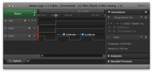
Here I used my logic analyzer to see how fast the code is running. Measuring the toggling of Pin 13 (line 101 in the code), I could measure the PWM frequency: about 5.6kHz.
Area for improvements
The #1 area I see for improvement is not using digitalWrite(). Especially when you get to more than 10 pins, it will start to slow things down. However, I couldn’t think of a way to create an area of “bits addresses” for direct port access. Until the PWM frequency gets too low, you probably don’t need to optimize here.
Another area is creating a function like “swAnalogWrite()” to change the PWN value, might be more readable.

7 Comments
Thanks for your clear example!
I’m working on an kinematic object whit LED lighting (present for my granddaughter). The hardware PWM did interfere with the IR receiver I use to control the LEDs and the speed of the object. Starting hardware PWM did mess up incomming IR codes. Implementing your code solved that problem.
During the implementation of your code I made three observations:
– Setting microInterval = 10; (old value was 250) resulted in a very smooth fade in fade out of the LEDs ;
– Using serialPrint (for debugging) inside a loop takes up a lot of time and introduced a lot of flickering LED’s. Making logging optional solved that issue.
– When all LED’s are off there was still a very dim light visible (equal to myPWMpins[index].pwmValue =1;).
When the Pinstate == ON and myPWMpins[index].pwmValue == 0, In the first iteration, digitalWrite should not be set HIGH.
Adding the following condition to line 98 – ” digitalWrite(myPWMpins[index].pin, myPWMpins[index].pinState” solved the problem
“if ((myPWMpins[index].pinState && myPWMpins[index].pwmValue > 0) || (!myPWMpins[index].pinState))”
Kind regars,
Ton Laarhoven
Hello
very interested in your program unsigned long currentMicros = micros (); with pwm,
I would like to order by sunrise: sunset a pin pwm led on a long time (4 hours without blocking the arduino card) could you help me find a code example
thanks in advance .
email: [email protected], france.
For a length of time in hours, you wouldn’t use micros(). You could use millis().
[arduino firstline=””]
unsigned long previousMillis = 0;
unsigned long interval = 1000UL * 60UL * 60UL; // Must specificy UL (unsigned long to get 3600000)
void() loop() {
unsigned long currentMillis = millis();
if (currentMillis – previousMillis >= interval) {
// one hour has passed
// do whatever you need to at that time
previousMillis = currentMillis; // reset the timer
}
}
[/arduino]
I meausured on oscilloscope.
With this code:
pin13 freq 1.96khz
other pwm pins with frequency 39hz
with microInterval=1
pin13 6.6khz
pwm pins 132hz
checked all with tester freq counter
so…not so fast
Hello.
Thanks for your article!
One question, though: if softPwm’s frequency is different from builtin hardware Pwm’s frequency, should I care about something in my code/circuit or this fact is in practice irrelevant? I mean…there’s no magic in hardware pwm’s frequency, isn’t?
PD: Maybe https://code.google.com/p/rogue-code/wiki/SoftPWMLibraryDocumentation is worthy to read in order to convert this code into a library (although project is abandoned)
In general, no the frequency won’t matter. However, there’s a few things to consider.
If you are controlling something like LEDs, the frequency affects how much flicker you might see. Faster frequency, less flicker. For motors, if the frequency is too fast the inductance of the windows may cause attenuation. The other concern is you could generate audible noise in the windings which tends to be more annoying with higher frequency.
Thanks for the Soft PWM Library link. I assumed there must be one already. I did, however, want to write this as a thought exercise and tutorial on how to use millis() and micros().
very interesting…I will need to read through this many times to better understand . Great work and thanks for sharing your talents.