Tag

Adafruit

Browsing

Funny how a simple idea can spider out into multiple paths. Arduino EEPROM seemed like a straightforward concept. A few a years ago it was as easy as having either 512 or 1024 bytes of flash memory. The Arduino IDE offered an EEPROM library which let you read and write a single byte. Today, however, with many different processor architectures saving data to EEPROM varies. It is now possible to save any datatype to EEPROM but not on all boards and not all using the same method.

While programming an coin accepter sold by Adafruit on an AddOhms live stream, I discovered two “new” methods in the Arduino library. At least, these functions are new to me! A couple of years ago EEPROM.get() and EEPROM.put() appeared. Using these functions, you can store any datatype in EEPROM.

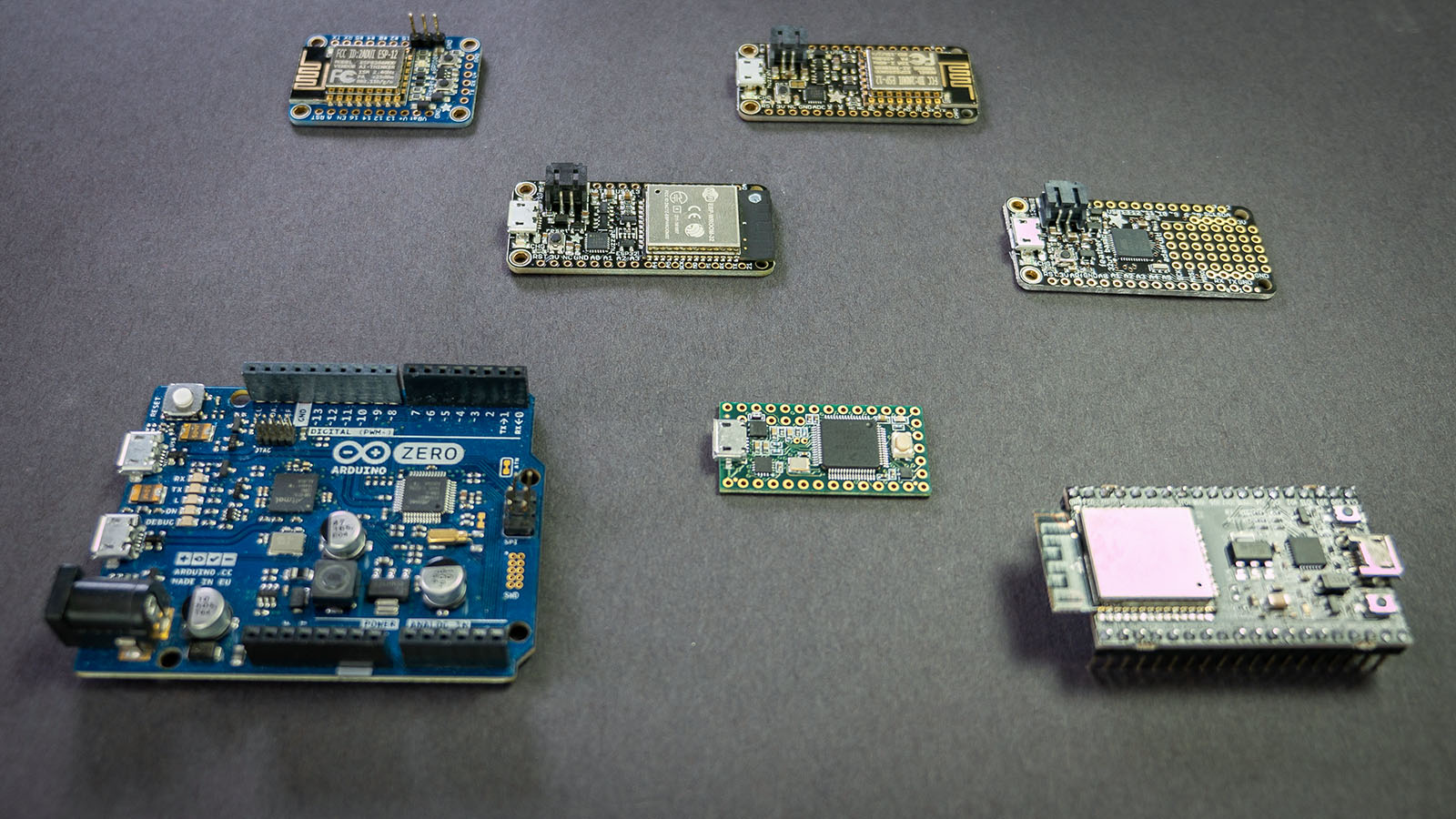
This post covers tidgets related to using Arduino EEPROM to store any value across multiple boards, or platforms. Specifically boards such as the Uno, Nano, Mega, and Zero are covered. Additionally Arduino-compatible boards from Espressif, PRJC, and Adafruit are covered as well.

Back in 2013, a Kickstarter ran for a project to put a python interpreter on a microcontroller. At the time I could not see the benefit. Cool project, but I asked myself: “why?” On my last Adafruit order, I received a free Circuit Playground Express. The board comes with CircuitPython pre-installed. After playing with Circuit Python, or CP, I finally “get it.”

For Valentine’s Day, I made an animated LED heart for a new love in my life, Circuit Python. Well, love is a bit of a strong word. The past couple of weeks I have been learning Circuit Python, and I am excited by what it offers.

What is Circuit Python?

It is a Python implementation that runs on microcontrollers. The code exists on the microcontroller as text. The interpreter runs the code from that text file. Circuit Python is built on, or based on, MicroPython. Adafruit is designing it to teach programming. It is easy to get started, just open up the code.py file from the auto-mounted drive and start typing. When you hit save, the code runs. That’s it.

While the buzzword “IoT “is relatively new, there has been a long time “internet of things” in operation. Those devices are called the far less sexy term “M2M” or machine-to-machine. These devices, around since the 90s, contain a microprocessor, some sensors, sometimes electromechanical hardware, and a cellular radio. These M2M devices were (and still are!) the early “Internet of Things.” Thanks to Hologram.io, you can join this new/old trend for free.

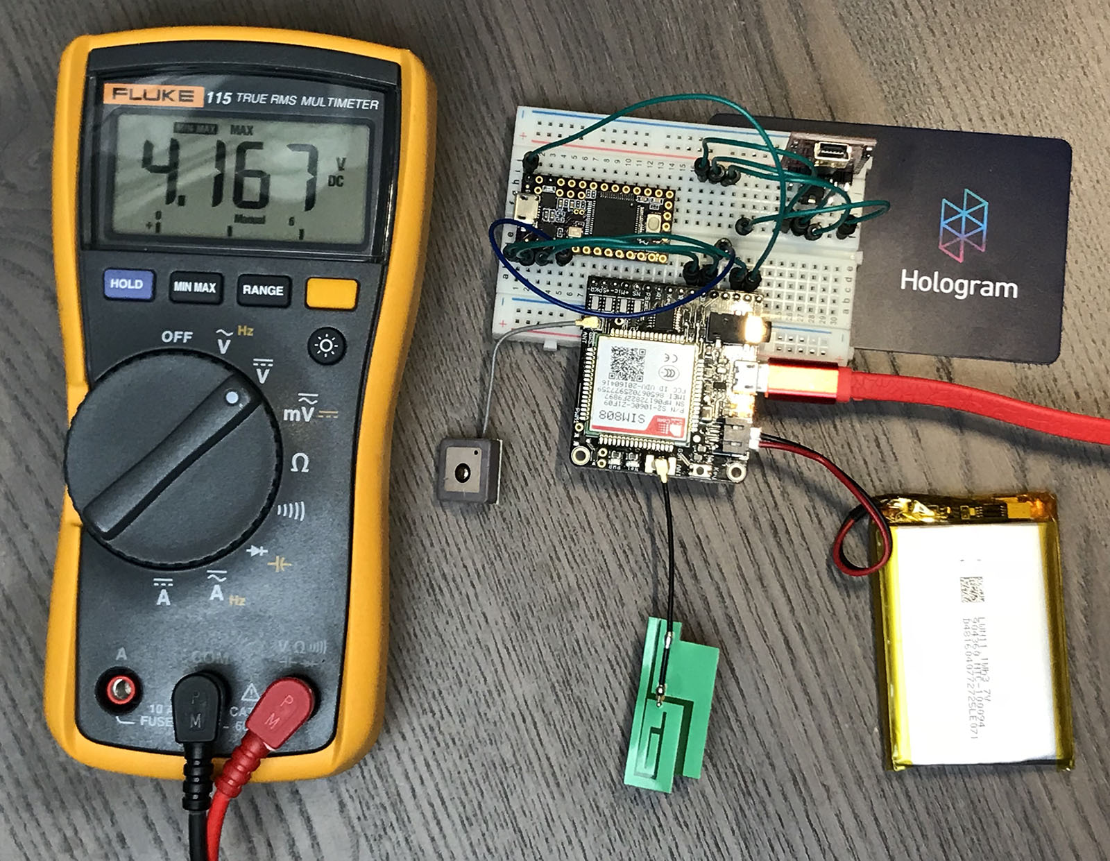
I decided it was time to up my IoT game with a GPRS, or 2G, data radio. In this post, I show the hardware I am using to create a 2G-based GPS tracker. It includes a Teensy 3.2 (Arduino) connected to a SIM808 Module (FONA) using a Hologram.io Developer SIM. It transmits GPS coordinates to an Adafruit.io Dashboard, which displays them on a map.

This post is not going to be a tidy tutorial. Instead, it is all the steps (and notes) I went through. I will cover:

  1. Hardware pieces I am using
  2. How to verify SIM808 (FONA) module is connected through Hologram via Serial Commands
  3. How to send HTTP/POST requests (including SSL) with the SIM808 (FONA)
  4. My (brute force) changes to the Adafruit FONA Library
  5. Code for sending MQTT payload (GPS Coords) to a dafruit.io dashboard

When done, you will be able to build something like a battery powered GPS Tracker, that updates over cellular. If you are in a rush, grab all the code from the FONA GPS Tracker Github Project.

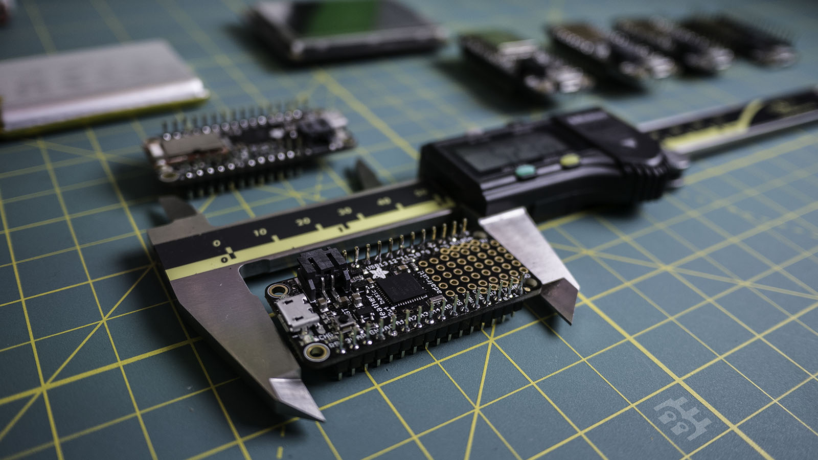
Four days ago, I found out I needed to make a piece of a costume. The idea was to combine a TFT LCD with a microcontroller and Bluetooth Low Energy. I checked my microcontroller bin and found some Adafruit Feather Boards. In this post, I will introduce the feather family and provide a decision chart for choosing the right one for your project.

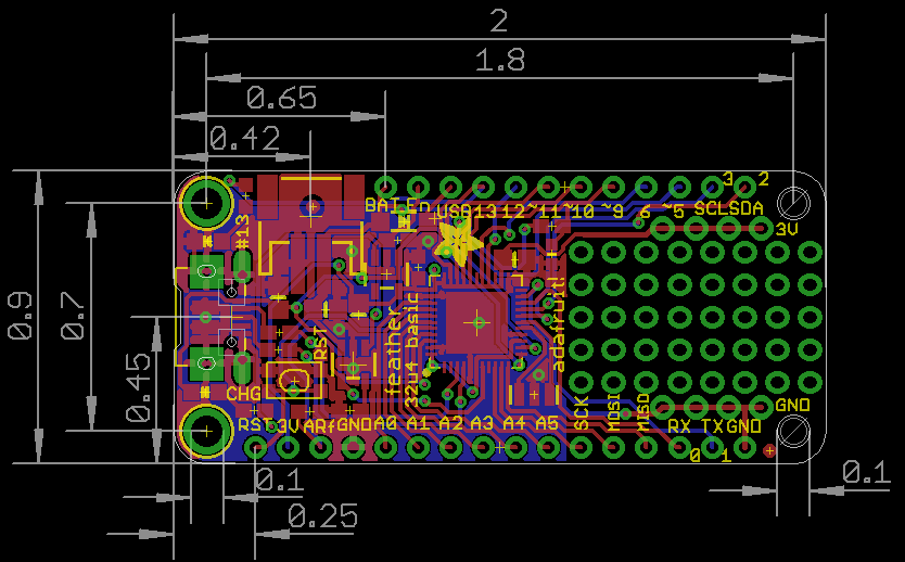
adafruit-feather-layout
Image from Adafruit Learning System

The Feather board have a standard footprint and pinout. Most(All?) have a USB connector, a microcontroller, two rows of pins, and a battery charger. They measure 50.80 by 22.86 mm, which is 2.0 by 0.9 inches.

Getting back to my IoT projects, I decided to pick up a temperature sensor. While looking through the Adafruit breakout boards, I found they offered nine different digital temperature sensors! This list is in addition to the analog TMP36 temperature sensor, so that’s ten. I needed an Adafruit Temperature Sensor comparison.

With so many options, I quickly found myself getting lost between the various modules. The 10 I found all measured temperature and provided an I2C interface. Except for the MCP9808 board, they all made at least one other type of measurement. The MCP9808 is the cheapest digital temperature sensor breakout that Adafruit offers, and also the most accurate.

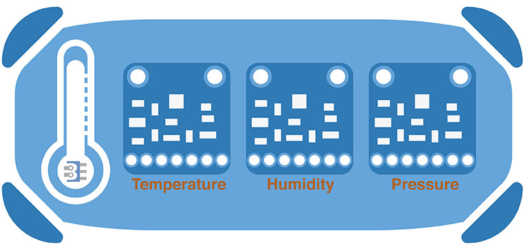
I couldn’t find a comparison in my quick search, so I built my own comparison table. Here’s my chart for an Adafruit Temperature Sensor comparison of their breakout boards.

adafruit temperature sensor comparison chart
Updated: 2016-JUL-27