
A DMM, or multimeter, is the go-to instrument for debugging most circuits. You probably already have at least one DMM on your bench for this reason. Me? I have three. But that’s a different story. Let’s talk about a Logic Analyzer.
Digital signals represent two states: on (usually “1”) and off (usually “0”). A multimeter (DMM) may be of limited value for these signals. When using the DC voltage measurement, you can see “something” is happening, but not exactly what that “something” is. For example on a PWM pin, you’ll see the RMS Voltage change as you modify the duty cycle. However, you can not see if the signal is “ringing” when turning on and off.
For debugging digital signals, a popular option is to use a Logic Analyzer. If you are not familiar with a logic analyzer, or you are not sure if you need one, this tutorial should help.
First I’ll give a simple overview of what a Logic Analyzer does, some considerations when to use one, and then give some terms to know when looking at them.
Logic Analyzer Basic Theory of Operation
The basic idea behind a logic analyzer is to sample multiple inputs, or channels, of data at the same, recording each channel’s state as a single bit. For example, if you have an 8-bit logic analyzer, each “sample” it will take 1 byte of data across all eight channels.
If you are familiar with analog-to-digital converters, then you can think of a logic analyzer channel as a 1-bit ADC. It can only store one value: on or off.
Oscilloscope vs. Logic Analyzer
Speaking of ADCs, let’s consider how a logic analyzer compares to a digital oscilloscope. Oscilloscopes typically have 2 or 4 channels. Logic analyzers, on the other hand, can have hundreds of channels.
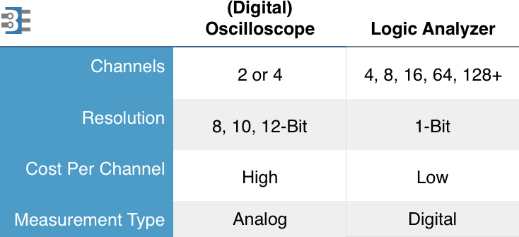
Although limited in channel count, a scope can have at least 8-bits of resolution on its analog-to-digital converter, giving it a high resolution of those few channels.
Logic analyzers provide you lots channels, but with limited resolution. Oscilloscopes provide you lots of resolution, but with limited channels.
Mixed Signal Oscilloscopes
Keep in mind there is one class of test equipment called a “Mixed Signal Oscilloscope”, or MSO. These combine logic analyzers and oscilloscopes into a single unit. A unique feature of an MSO is that it can “time correlated” the analog channels to the digital channels. These are fantastic tools when doing work that crosses the analog and digital domains.
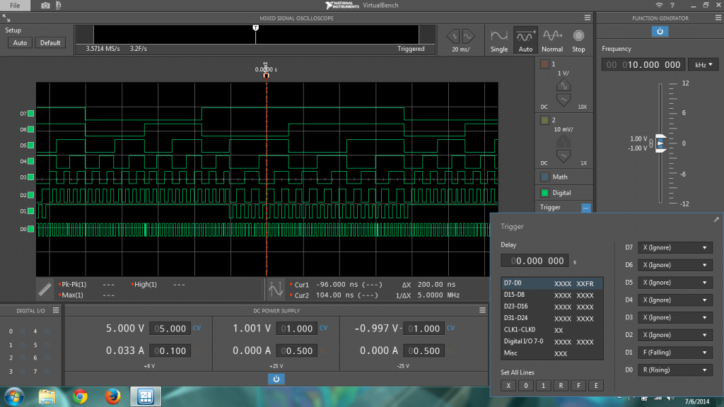
Check out my review on the VirtualBench from NI for a short introduction on MSOs. You can also check out my “MSO Demo Board” project.
Uses for Logic Analyzers
Obviously, the primary use of a logic analyzer is to look at digital signals. Years ago they were incredibly attractive when debugging the wide memory and I/O busses of digital systems like 32-bit computer systems. With more embedded device using System On a Chip (SOC) designs, these wide busses are not broken out, leaving less opportunity to use a logic analyzer.
That said, there are still a few potential measurements for a Logic Analyzer.
Multiple Serial Buses: I2C, SPI, and UART
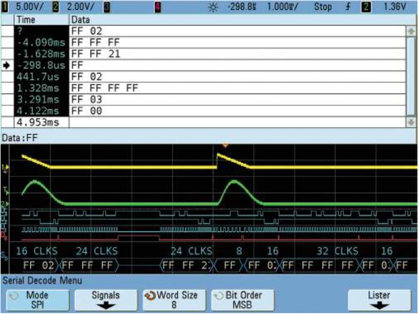
One of the powerful capabilities of a logic analyzer is “time correlating” a large number of signals on a single display. This data view is very helpful to watch data move around inside of an embedded system.
For example, you may watch data come into a microprocessor’s UART and then back out to an SPI device, perhaps EEPROM, and then finally a piece of data out to an I2C device. On a logic analyzer, watching all of these buses over an extended period is possible.
Low-Cost GPIO Debug
The cost-per-channel for oscilloscopes is much higher than the cost per channel-for-logic analyzers. A logic analyzer can be a relatively quick and very simple way to connect to some digital GPIO pins to see what they are doing. Sometimes it may be enough to see a signal is “glitching” (transitioning when it shouldn’t) to see something is wrong.
Logic Analyzer Terms
If you’re looking to add a logic analyzer to your electronics bench, then here are some terms to help understand logic analyzers.
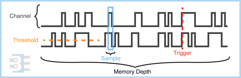
Voltage Thresholds
The logic threshold is the voltage level that decides if a signal is a “1” or a “0”.
Samples
The data the logic analyzer captures. Each time the logic analyzer samples data, it samples across all of its channels simultaneously. So if you have eight channels, that means each “sample” will be 1-byte worth of data.
Sample Rate
The sample rate is how often a logic analyzer samples all of its channels. Speeds for logic analyzers can be all over the place. Today it is common to see analyzers in the “megasample” range. The low-cost Logic 8 from Saleae, for example, has a maximum sample rate of 100 Megasamples per second (Msps).
Sometimes Logic Analyzers advertise their sample rate in “Megahertz” instead “Megasamples.”
Record Length or Memory Depth
When sampled, the data collect has to go somewhere. In stand-alone logic analyzers, this memory is built into the acquisition front-end. For a USB logic analyzer, it is common to stream the data over USB back to the PC. This method has the benefit of virtually unlimited storage. The trade-off is, if the USB bus gets busy, data loss could happen. It also fundamentally limits the maximum sample rate.
Sampling Modes: State vs. Timing
If you are looking at lower-end USB-based logic analyzers, you may not have an option for the sampling mode. Instead, the analyzer may always be operating in “timing mode”. Another name that is used is “asychronous mode.” This mode means the logic analyzer samples at its programmed speed, displaying what it saw.
Mid-Range to high-end logic analyzers often offers a special mode called “State Mode.” In this mode, one of the inputs is used as a “clock” signal. The clock tells the logic analyzer when to “sample” the data channels. The idea is for the logic analyzer to sample the data the same way the system under test does.
I should also point out that some logic analyzers do both at the same time. They asynchronously sample the data and then reconstruct state mode data from those samples.
Triggers
One of the most powerful capabilities of a solid logic analyzer is the ability to trigger. The logic analyzer watches the sampled data for user-defined patterns. When these patterns occur, a trigger event happens. Once “triggered” the logic analyzer stops sampling or finishes filling its data buffer.
A simple trigger might be matching a pattern or a signal’s edge direction. A complex trigger would be setting up a series of conditions, like if-statements to look conditionally look for patterns.
An example of a complex pattern might be, you want to trigger when a certain data pattern comes across the data bus after an address goes across an address bus. You would need some logic to create the if-then structure.
Logic Analyzers I Have
On my bench, I have two logic analyzers. My most popular logic analyzer is a Logic 4 from Saleae. The is the analyzer I used to benchmark Arduino’s digitalWrite. The Logic is a simple USB device with fixed input thresholds. Triggering is limited to edge direction and pulse width violations. However at about $100 it is cheap, quick, and simple to see what my Arduino’s GPIO pins are doing.
My other logic analyzer is an LAP-C from ZeroPlus. Compared to the Logic 4, it is a full featured logic analyzer. However, its Windows-only software is far more complex to use. On the other hand, it has many features found in high-end analyzers at a cost close to the Logic 4. But don’t just look at the price. As it turns out, I rarely use it. The LAP-C is relatively complex to setup. Though, I appreciate the power of its protocol decode, more advanced triggers, and wide channel counts when I do use it.
Other logic analyzer options
There is an open-source project called sigrok. It is a logic analyzer application. Sigrok connects to several hardware options like the Bus Pirate from Dangerous Prototypes and offers a very low-cost method for doing logic analysis.


1 Comment
Thankns for your simple tutorial. Even laptop power supplies are now using single-wire protocol to allow power flow from a DC supply to a laptop. I bought a simple logic analyzer to look at the data flow to simulate a Dell power supply. Many other uses for UART-based controllers and PWM timing for stepper motors come to mind. The logic analyzers are so cheap and powerful that it makes sense to have one available.