Tag

Logic Analyzer

Browsing

Analog Discovery Pro from Digilent comes in a 2-channel (ADP3250) or 4-channel (ADP3450) version. These all-in-one instruments work with a PC over USB or can run entirely standalone.

On the PC the excellent Waveforms software provides virtual instruments like an Oscilloscope, Logic Analyzer, Power Supply, Spectrum Analyzer, Curve Tracer, Network Analyzer, and Impedance Analyzer. Just to name a few. See what this new instrument offers in this hands-on review.

This episode was sponsored by Digilent.

Logic analyzers capture digital signals and then display a waveform or list. Serial busses like I2C, SPI, or UART (Serial) can be decoded or triggered on when there are problems in your circuit. In this video, learn the basic controls you need to use (almost) any logic analyzer. You’ll learn how to set up a simple trigger, make measurements, and set things like sample rate or memory depth.

When I first graduated from college, I started as an Application Engineer for Agilent Technologies. Based in Austin, I supported computer companies like Dell, Compaq, HP, IBM, and Tandem. I helped their engineers set up million-dollar logic analyzer configurations to measure various PC busses.

I did embellish a tad during the introduction. Shown in the video is an HP 16500. While I did occasionally help program a trigger on these analyzers, my career really started with its successor, the HP 16700. Both were amazing analyzers for their time. It is mind-boggling to think that a small $150 USB-based device has very similar measurement capabilities to those old beasts.

Previously, I made a written Logic Analyzer introduction tutorial and benchmarked digitalWrite() with a Salee Logic 8. Contrary to what people have said, the LA2016 featured in this video does NOT use Salee’s excellent Logic software. However, the user interface is clearly copied from it.

See show notes on element14

A DMM, or multimeter, is the go-to instrument for debugging most circuits. You probably already have at least one DMM on your bench for this reason. Me? I have three. But that’s a different story. Let’s talk about a Logic Analyzer.

Digital signals represent two states: on (usually “1”) and off (usually “0”). A multimeter (DMM) may be of limited value for these signals. When using the DC voltage measurement, you can see “something” is happening, but not exactly what that “something” is. For example on a PWM pin, you’ll see the RMS Voltage change as you modify the duty cycle. However, you can not see if the signal is “ringing” when turning on and off.

For debugging digital signals, a popular option is to use a Logic Analyzer. If you are not familiar with a logic analyzer, or you are not sure if you need one, this tutorial should help.

First I’ll give a simple overview of what a Logic Analyzer does, some considerations when to use one, and then give some terms to know when looking at them.

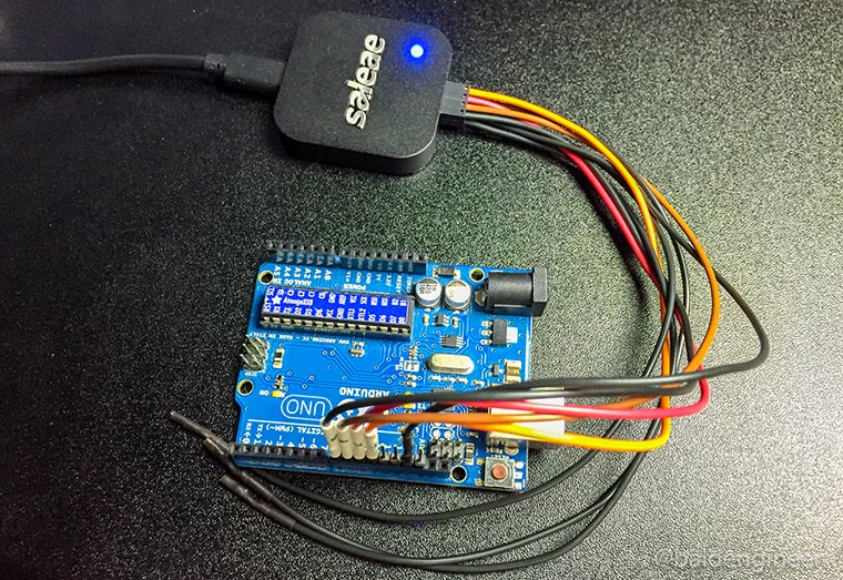
Recently I picked up a device called Logic from Saleae. It’s a 4-channel USB-based logic analyzer. While learning how the simple, but effective, UI works I ran some timing benchmarks on my Arduino Uno. The subject? digitalWrite(). I wanted to know how fastdigitalWrite() could turn on two (or more) pins.

Almost all Arduino users start out with the simple “blink” sketch. Turn pin 13 ON, delay, turn it OFF, and delay again. The heart of this version of “Hello World!” is the digitalWrite() function. Many Arduino users never even think about all of the stuff this single function call hides.

In this post, let’s compare the speed of digitalWrite() to direct port manipulation, using a logic analyzer.