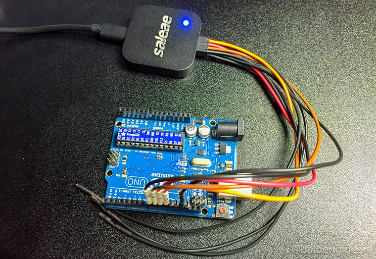
A DMM, or multimeter, is the go-to instrument for debugging most circuits. You probably already have at least one DMM on your bench for this reason. Me? I have three. But that’s a different story. Let’s talk about a Logic Analyzer.
Digital signals represent two states: on (usually “1”) and off (usually “0”). A multimeter (DMM) may be of limited value for these signals. When using the DC voltage measurement, you can see “something” is happening, but not exactly what that “something” is. For example on a PWM pin, you’ll see the RMS Voltage change as you modify the duty cycle. However, you can not see if the signal is “ringing” when turning on and off.
For debugging digital signals, a popular option is to use a Logic Analyzer. If you are not familiar with a logic analyzer, or you are not sure if you need one, this tutorial should help.
First I’ll give a simple overview of what a Logic Analyzer does, some considerations when to use one, and then give some terms to know when looking at them.


