Unless you have a BNC or SMA connector your board, you will need a probe to get signals into an oscilloscope. Understanding what kind of oscilloscope probes are out there, which ones should you have for your scope and which ones to use for different measurements can be daunting. In this post, I look at some common scope probe types and offer some suggested measurements for each.
Special thanks to Rohde and Schwarz for providing the equipment used in this post. You can learn more about their scopes and probes at rohde-schwarz.com .
This post is not a comprehensive guide of oscilloscope probes. I am covering the types I have used. I do think this information should be enough to least form questions to ask your vendor before purchasing. Asking questions is important. If you have never bought specialized oscilloscope probes, you might not realize they can cost more than the scope itself. Maybe not an individual probe, but get one for each channel, and the cost rises. So picking the correct probe type is essential.
My recent SONOFF WiFi Switch experience reminded me of something from high school. I attended an off-site electronics class with my best friend. As teenage boys, we were prone to doing stupid things. One of our favorite games was to see who could handle the highest voltage. Our bench had a variable AC supply that went from 0 to 120 volts. So we would grab the alligator clips while the other person slowly turned the knob up. John once made it to 50 volts. I seem to recall my tolerance around 30 volts. First, DO NOT do this. It was stupid. Second, I think this game is why handling AC makes me so uncomfortable.
While I am not an electrician, I do know the basics about wiring mains AC circuits. So when one of my studio lights needed a new switch, I was okay to replace it. Mains AC does not scare me when it is off. I did not have a mechanical switch available. Instead, I opted for a SONOFF WiFi Switch. I did not intend to connect WiFi, at least not yet. I just wanted to control the light with the manual push button.
The clever solution seemed to be clever, at least for a few minutes. Suddenly the light turned off. I thought maybe there was a timeout for the manual button. Annoying, but workable. The lamp remained off for about another 2 minutes when I started to smell that unmistakeable burning plastic odor. Touching the case of the SONOFF identified the culprit immediately.
Great. So I have an AC mains switch that isn’t working, but I do not want to go poking my multimeter into it. What do I do?
Turns out, that SONOFF module was defective. I wanted to debug it, but I did not want to measure anything while connected to AC. Here’s how I used a thermal camera to debug my SONOFF.
What is a SONOFF?
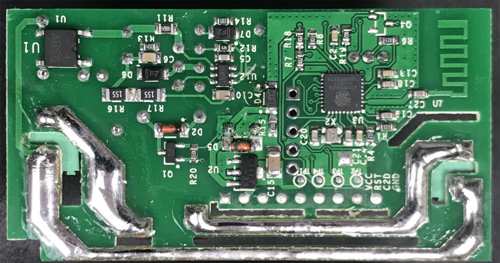
See the ESP8266 and Antenna?
The SONOFF WiFi switch is an inexpensive AC relay. Internally it has an ESP12 chip, which became popular with the ESP8266. There is even an unpopulatd serial header which can be used to reflash the firmware. Among hackers, these modules are a popular way to get an AC relay that is easily programmed.
Supplyframe Hardware has published a video of a talk I gave in July 2017. This talk was at HDDG 22. The focus of my discussion was how an oscilloscope’s trigger circuit works. I built on that and talked about some of the behind-the-scenes stuff of what is going on with a digital oscilloscope. (You can download my HDDG 22 slides here.)
For fifteen years I used my Radio Shack 22-168A digital multimeter as my go-to meter. A couple of years ago I bought a Fluke 115. Not because the RS meter lacked a measurement, but because I wanted a backlit screen. Here’s the crazy thing though in 20 years of multimeter development, there hasn’t been much innovation. Well outside of maybe auto-ranging.
All three meters I have, plus the Virtual Bench I reviewed about a year ago all continue to have the same limitation: they can only perform one measurement at a time. That’s one feature that makes my latest meter, the Mooshimeter, unique. It can measure both voltage and current at the same time. Oh, and it doesn’t have a screen.
A DMM, or multimeter, is the go-to instrument for debugging most circuits. You probably already have at least one DMM on your bench for this reason. Me? I have three. But that’s a different story. Let’s talk about a Logic Analyzer.
Digital signals represent two states: on (usually “1”) and off (usually “0”). A multimeter (DMM) may be of limited value for these signals. When using the DC voltage measurement, you can see “something” is happening, but not exactly what that “something” is. For example on a PWM pin, you’ll see the RMS Voltage change as you modify the duty cycle. However, you can not see if the signal is “ringing” when turning on and off.
For debugging digital signals, a popular option is to use a Logic Analyzer. If you are not familiar with a logic analyzer, or you are not sure if you need one, this tutorial should help.
First I’ll give a simple overview of what a Logic Analyzer does, some considerations when to use one, and then give some terms to know when looking at them.
Like other websites, this one uses cookies to remember things. Mostly, I use Google Analytics to know how many people come here. ¯\_(ツ)_/¯
By clicking “Accept”, you consent to the use of ALL the cookies.
This website uses cookies to improve your experience while you navigate through the website. Out of these, the cookies that are categorized as necessary are stored on your browser as they are essential for the working of basic functionalities of the website. We also use third-party cookies that help us analyze and understand how you use this website. These cookies will be stored in your browser only with your consent. You also have the option to opt-out of these cookies. But opting out of some of these cookies may affect your browsing experience.
Necessary cookies are absolutely essential for the website to function properly. These cookies ensure basic functionalities and security features of the website, anonymously.
Cookie
Duration
Description
cookielawinfo-checkbox-advertisement
1 year
Set by the GDPR Cookie Consent plugin, this cookie is used to record the user consent for the cookies in the "Advertisement" category .
cookielawinfo-checkbox-analytics
11 months
This cookie is set by GDPR Cookie Consent plugin. The cookie is used to store the user consent for the cookies in the category "Analytics".
cookielawinfo-checkbox-functional
11 months
The cookie is set by GDPR cookie consent to record the user consent for the cookies in the category "Functional".
cookielawinfo-checkbox-necessary
11 months
This cookie is set by GDPR Cookie Consent plugin. The cookies is used to store the user consent for the cookies in the category "Necessary".
cookielawinfo-checkbox-others
11 months
This cookie is set by GDPR Cookie Consent plugin. The cookie is used to store the user consent for the cookies in the category "Other.
cookielawinfo-checkbox-performance
11 months
This cookie is set by GDPR Cookie Consent plugin. The cookie is used to store the user consent for the cookies in the category "Performance".
CookieLawInfoConsent
1 year
Records the default button state of the corresponding category & the status of CCPA. It works only in coordination with the primary cookie.
viewed_cookie_policy
11 months
The cookie is set by the GDPR Cookie Consent plugin and is used to store whether or not user has consented to the use of cookies. It does not store any personal data.
Functional cookies help to perform certain functionalities like sharing the content of the website on social media platforms, collect feedbacks, and other third-party features.
Cookie
Duration
Description
language
session
This cookie is used to store the language preference of the user.
Performance cookies are used to understand and analyze the key performance indexes of the website which helps in delivering a better user experience for the visitors.
Analytical cookies are used to understand how visitors interact with the website. These cookies help provide information on metrics the number of visitors, bounce rate, traffic source, etc.
Cookie
Duration
Description
_ga
2 years
The _ga cookie, installed by Google Analytics, calculates visitor, session and campaign data and also keeps track of site usage for the site's analytics report. The cookie stores information anonymously and assigns a randomly generated number to recognize unique visitors.
_ga_LHR6J24XSY
2 years
This cookie is installed by Google Analytics.
_gat_gtag_UA_42726312_1
1 minute
Set by Google to distinguish users.
_gid
1 day
Installed by Google Analytics, _gid cookie stores information on how visitors use a website, while also creating an analytics report of the website's performance. Some of the data that are collected include the number of visitors, their source, and the pages they visit anonymously.
browser_id
5 years
This cookie is used for identifying the visitor browser on re-visit to the website.
CONSENT
2 years
YouTube sets this cookie via embedded youtube-videos and registers anonymous statistical data.
Advertisement cookies are used to provide visitors with relevant ads and marketing campaigns. These cookies track visitors across websites and collect information to provide customized ads.
Cookie
Duration
Description
VISITOR_INFO1_LIVE
5 months 27 days
A cookie set by YouTube to measure bandwidth that determines whether the user gets the new or old player interface.
YSC
session
YSC cookie is set by Youtube and is used to track the views of embedded videos on Youtube pages.
yt-remote-connected-devices
never
YouTube sets this cookie to store the video preferences of the user using embedded YouTube video.
yt-remote-device-id
never
YouTube sets this cookie to store the video preferences of the user using embedded YouTube video.
yt.innertube::nextId
never
This cookie, set by YouTube, registers a unique ID to store data on what videos from YouTube the user has seen.
yt.innertube::requests
never
This cookie, set by YouTube, registers a unique ID to store data on what videos from YouTube the user has seen.