
My recent SONOFF WiFi Switch experience reminded me of something from high school. I attended an off-site electronics class with my best friend. As teenage boys, we were prone to doing stupid things. One of our favorite games was to see who could handle the highest voltage. Our bench had a variable AC supply that went from 0 to 120 volts. So we would grab the alligator clips while the other person slowly turned the knob up. John once made it to 50 volts. I seem to recall my tolerance around 30 volts. First, DO NOT do this. It was stupid. Second, I think this game is why handling AC makes me so uncomfortable.
While I am not an electrician, I do know the basics about wiring mains AC circuits. So when one of my studio lights needed a new switch, I was okay to replace it. Mains AC does not scare me when it is off. I did not have a mechanical switch available. Instead, I opted for a SONOFF WiFi Switch. I did not intend to connect WiFi, at least not yet. I just wanted to control the light with the manual push button.
The clever solution seemed to be clever, at least for a few minutes. Suddenly the light turned off. I thought maybe there was a timeout for the manual button. Annoying, but workable. The lamp remained off for about another 2 minutes when I started to smell that unmistakeable burning plastic odor. Touching the case of the SONOFF identified the culprit immediately.
Great. So I have an AC mains switch that isn’t working, but I do not want to go poking my multimeter into it. What do I do?
Turns out, that SONOFF module was defective. I wanted to debug it, but I did not want to measure anything while connected to AC. Here’s how I used a thermal camera to debug my SONOFF.
What is a SONOFF?
The SONOFF WiFi switch is an inexpensive AC relay. Internally it has an ESP12 chip, which became popular with the ESP8266. There is even an unpopulatd serial header which can be used to reflash the firmware. Among hackers, these modules are a popular way to get an AC relay that is easily programmed.
The Dilemma
Because time was critical, I just hardwired the lamp and threw the SONOFF aside. Yesterday I had some time before leaving on a business trip and got back to thinking about the module. Was it a fluke or was the module supposed to get that hot? If there was a short, why didn’t the AC circuit breaker trip? Also, is there really an ESP8266 inside of these things?
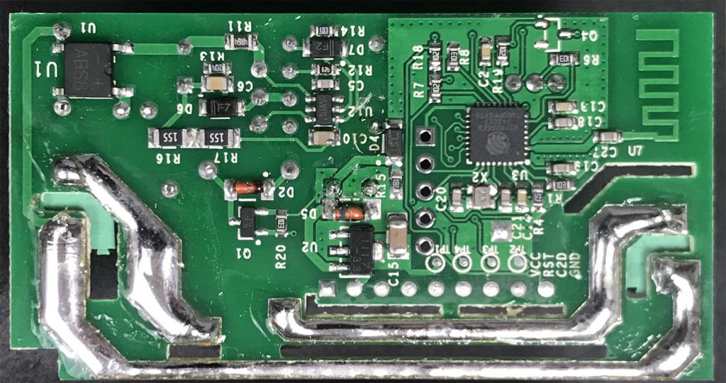
The problem is that I do not like taking measurements on AC. So after disassembling the board, I visually inspected it, but saw no issues. I did not see any shorts. I did not see any burned components. After shorting the two electrolytic caps, I knew it was reasonably safe to poke around the board with my Mooshimeter.
There wasn’t a short on the AC input or output, so that explains why there wasn’t a circuit breaker fault. By the way, I gave it a light scrub with alcohol to remove any flux residue. That step didn’t help. From there, I was not sure where to start. I did, however, see the distinctive in-situ PCB antenna and Espressif Systems SoC.
Thermal View
That is when I remembered I have a Flir One Thermal Camera attachment for smartphones. (They are selling the Gen 3 as of this post, I have an earlier version.) Until now, I have only used it to verify my HVAC was not working, and my 3d printer’s stepper motors got hot.
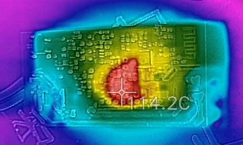
I pointed the camera at the PCB, plugged it in and saw this happen.
That area of the board got hot and fast. It was a simple NCP1117 linear regulator. I am not sure, but I believe it was a 3.3 volt output. The camera showed over 110°C on both sides of the PCB in that area. So either the SONOFF’s design sucks or something is wrong. At least now I had a place to start poking probes, while the board is unplugged.
I found that there was only a 33 ohm impedance between the NCP1117’s output and ground. You know the adage, “when you only know how to use a hammer, everything looks like a nail?” Well, I suspected the 470uF 16V electrolytic capacitor on the regulator’s output. I desoldered it and to my surprise! It was fine. In fact, my meter measured 500uF. Now I am not sure if the meter is off or if the cap is higher than rated, but still within tolerance. Either way, its leakage current was relatively low. So that capacitor is in good shape. Also, the 33 ohm impedance remained after removing the cap.
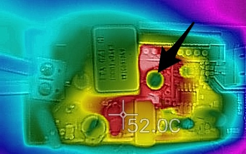
The other neon-red clue the capacitor was probably okay is the thermal picture from the other side. The big bright dot is the top of the capacitor. While its outside edge is heating up, the core is not.
Need a known good SONOFF
At this point, I had two choices: either start probing the board live or compare to a known good module. Luckily, when ordering cheap junk, I always order two. (My favorite quote from the movie “Contact” is “Why build one, when you can have two for twice the price?”) I added a cable, plugged it in and noticed two spots that heat up: the linear regulator and the ESP12 chip.
Now the key difference here is that both spots reach steady state between 30 and 40°C. Significantly less than what I saw with the other module. Also, the heat is limited to the two local heat sources. While this single data point does not let me state “this one works correctly,” it is behaving differently. For this comparison, let’s call this the “good module.”
Comparing the two modules, it appeared that spots on the boards heated up at about the same time. Which means, I couldn’t use just the thermal images to identify a short circuit. The fact that the heat-up patterns are about the same, combined with not finding a failed passive component, I am now suspecting the linear regulator itself.
Conclusion
I did not have time to replace the NCP1117. I elected not to remove it all because I do not have a replacement. But, my next step is removing the regulator to see if there is still a 33 ohm impedance on that voltage rail. If I am careful enough, I should be able to put it back in case I am wrong.
Debugging with a thermal camera allowed me to check various points on the circuit, identify potentially faulty components, and never once did I have to touch anything while this unprotected board was connected to AC mains voltages.
What else should I check? Have you had issues with these SONOFF modules? What tips do you have for debugging AC circuits safely?


18 Comments
I try to measure the voltage before and after rectifier, and you know, from 220 ac voltage changed to 310 dc voltage, and it was lot of work for the circuit to cut them down so the digital pwm ic can run the aux from the bias winding at transformers.
After reading your article it make me no wonder at all. By the way, i’m in case to learn more about this digital pwm current-mode, if you have another good article let me know.
thanks
Well, thank you for the legwork. (I should have looked up the data sheet on the iW1710.) Definitely don’t understand that reference design. Will put it into “2nd year electronics circuits” folder to learn about later.
Got two this weekend and fired one up to see if it exhibited any overheating issues. With my CHEAP (~$39) Harbor Freight IR temperature gun, I saw the regulator stabilize at 103ºF with the relay on. The ESP was well below that.
I have some questions:
1) How did you figure out the regulator was a 1117? Mine was marked 1511-36 5247047 UB1542. I could not get any of those numbers to come up as a regulator in Digi-Key.
2) Has anyone taken a stab at deducing a schematic for the device?
3) The pairing process makes me a little uncomfortable. I had to use the “Compatible Pairing Model (AP)”. I had to do something similar to get my Honeywell WiFi thermostat connected, I remember. What concerns me is how do we know that our SSID and WiFi password aren’t sent back to China? I wish someone more adept at Wireshark than me could look at that. I mean they could come from Shenzhen and park outside my house in the Twin Cities and use up my Internet quota! Or worse! 🙂
Now to decide what I would like to be able to remotely control.
Rick
That sounds about right and similar to my “working” module.
Mine were marked “1117” so I just took a guess. Pin out matched, as I recall.
I haven’t looked for one. The AC-DC circuit should be easy to sketch out. The 8266’s pinout might be more difficult to trace. I wouldn’t be surprised if a schematic is out there.
I intended to replace the Chinese firmware with something else. I just had not decided on the something else yet. Ideally, I just want it to subscribe to my MQTT server and respond to messages I post there. I don’t like my IoT devices having access to the I. 😉
Who would have thought! Schematic at vendor site: https://www.itead.cc/wiki/images/f/ff/Sonoff-Schematic.pdf
Confusing to me. E.g. transformer downstream of full wave rectifier and filters?
Maybe it is so that they can use a smaller and cheaper transformer.
But with the transformer downstream of the full-wave rectifier and an LC smoothing network, how could the transformer work? They need AC to connect the primary voltage to the secondary.
Well sure, there is that one little detail. 😉 Might be worth (carefully) poking around the circuit a bit to understand it better.
After looking at the schematic a bit more, it looks like a typical flyback circuit. The small LC network on the primary side is probably for EMI and not for smoothing. The rest of the circuit on the primary side is almost identical to the IW1710’s reference design. The IW1710 is an AC/DC supply controller that works without the opto-isolator. (Which would normally be connected to the other half of the secondary.)
Hi James, Great article. I also have a smartphone connected thermal camera (Seek compactXR), which is one of the first tools I turn to when fault finding any board with excess current consumption.
It’s worth noting that the electrolytic capacitor that you highlight as running cool may not be cooler than other components on the board. A trap with thermal cameras is that reflective metal surfaces will not produce an accurate measurement. I think the shiny surface is reflecting the IR ambient conditions from around the device under test – acting as an IR mirror.
I suspect the 33 Ohms on the regulator output is not the problem, as at 3.3V, this would not result in the power dissipation you have observed.
I wonder whether the power supply is using a resistor and capacitor (probably a 0.22 – 0.47uF X2 film capacitor) to drop the mains voltage before the bridge rectifier. If there was a failure in this part of the circuit, the 1117 regulator may be seeing a higher input DC voltage than intended, and dissipating excessive energy. The thermal camera would make it appear that the problem was at the regulator instead of the AC input voltage dropping circuit.
Cheers,
Dave
Hi Dave, good tips! I think I will try soldering a wire to the 1117 to verify its input while live. I think your idea of the rectifier would fit with the behavior after the regulator.
And I’ll bet you are right about the capacitor appearing to be running cool.
I’ve bought 5 and played around with one on the bench. I took a chance and left it on Standby so I could prove in days to come, that I could operate it from a rental house, via the app on the android phone. It worked. got home and put it away. Now you have me worried! I have a laser temperature gun which I will use when I power up each unit. Find a retired TV technician and buy his AC isolation transformer – else trace the AC input past it’s zener regulators (usually) and carefully measure the rectified DC voltage across the filter capacitor (clip leads). Then provide your own DC volts to this capacitor leaving the mains unplugged. I also use a portable RCD safety switch (here in Australia , 240volts M.E.N electrical system).
Regards, Jim Templeton.
Great idea on supplying the DC while unconnected.
I didn’t get into the details, but when the regulator starts going past 110C, it appears to be shutting down. The ESP12 starts to reboot and the relay disconnects. So it is obvious there is a problem even before noticing the temperature.
That’s a great idea. What thermal camera are you suing? Can you recommend a reasonably priced one?
He tells you. Hit Ctrl F and type FLiR.
I’m using the FLIR One Pro attachment for smartphones. There is one for iOS (Lightning) and Android (USB-C). It is still about $400 for that module. But cheaper than a full FLIR.
But you do have a replacement NCP1117…
Haha, yes, I suppose I do. I hadn’t thought about that.