
Unless you have a BNC or SMA connector your board, you will need a probe to get signals into an oscilloscope. Understanding what kind of oscilloscope probes are out there, which ones should you have for your scope and which ones to use for different measurements can be daunting. In this post, I look at some common scope probe types and offer some suggested measurements for each.
This post is not a comprehensive guide of oscilloscope probes. I am covering the types I have used. I do think this information should be enough to least form questions to ask your vendor before purchasing. Asking questions is important. If you have never bought specialized oscilloscope probes, you might not realize they can cost more than the scope itself. Maybe not an individual probe, but get one for each channel, and the cost rises. So picking the correct probe type is essential.
Terms for Oscilloscope Probes
There are a few terms and characteristics you need to understand when selecting scope probes.
Bandwidth
Bandwidth defines the range of signal content the probe can capture. For example, a 10 MHz clock signal, which is a square wave, requires 50 MHz of bandwidth to characterize it accurately. The reason is that multiple sine waves make up a square wave. In this example, that would be 10 MHz, 30 MHz, and 50 MHz combined. If you measure a 10 MHz square wave with a 10 MHz probe, you will only see the fundamental sine wave.
When scopes and oscilloscope probes rate bandwidth at their -3db point. This point means the frequency where the signal loses about 30% of its amplitude. As frequency goes up, this loss gets higher.
Dynamic Range (Voltage Range)
The vertical or voltage range is the maximum voltage the probe can measure.
Probes may be rated for the range which they can measure as well as a range which will damage the probe. Do not mix up these ranges.
Offset Voltage
With active probes, the probe itself may be able to introduce a voltage offset to the signal under test. An offset voltage “moves” a signal inside of the probe’s dynamic range.
For example, if you measure the 5 volt DC rail of a switching regulator, you may be interested in the AC ripple voltage. A negative voltage offset in the probe allows expanding the ripple across the probe’s amplifier and the scope’s A/D range.
Impedance (and loading)
It is impossible to measure a circuit without affecting it. When attaching anything, even your multimeter’s leads, the circuit changes. In simple terms, you can think of a probe as a resistor and a capacitor.
Voltage probes almost always specify their resistive and capacitive loading. (Impedance is the complex form of resistance.) Think of these values as an RC-circuit attached to the device under test.
Voltage vs. Current vs. Temperature vs. ???
Oscilloscopes measure voltage. With an appropriate adapter or probe, you can measure other physical quantities. A typical example is a current probe. Guess what it does! You could also look at temperature or optical signals with an appropriate adapter.
For the most part, I will discuss voltage probes. I will touch on current probes but wanted you to be thinking about what else you could measure with an oscilloscope.
Passive Oscilloscope Probes
Generally, when you buy an oscilloscope, it comes with some probes. Depending on the price class of the instrument these probes may be matched to the same bandwidth of the scope or less.
Standard / General Purpose
I am not sure the exact name to call these passive oscilloscope probes. So I will use “standard” or “general purpose.” These are what you probably picture when you think “scope probe.”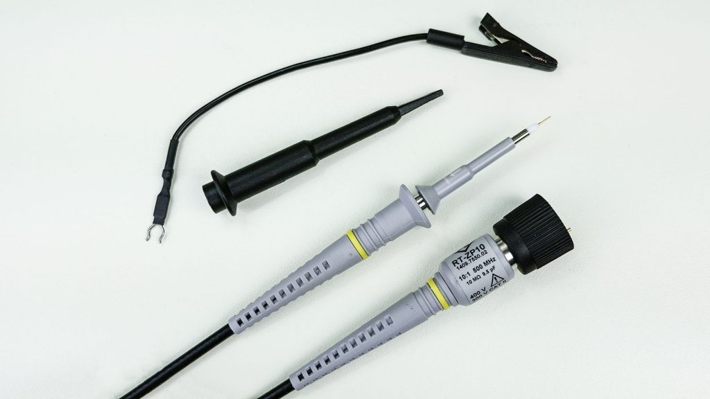
While other bandwidths exist, the one I see most is 500 MHz. Generally, the impedance is at least 10 MΩ with capacitive loading around 10 pF. My RTM3004 came with the R&S RT-ZP10. Their impedance is 10 MΩ, and their capacitive loading is 9.5 pF.
Most passive oscilloscope probes are a 10:1 voltage divider. This ratio means the signal at the probe tip is 10 times larger than the signal at the scope’s front-end BNC. (Or said another way, the scope gets a signal 1/10th the original signal’s voltage.) Why is that divider important?
Why a 10-to-1 divider?
First, the 10:1 divider is useful because you can measure high-voltage signals with the oscilloscope. If the scope’s maximum input voltage is 10 volts, with a 10:1 probe attached it is possible to measure up 100 volts. The probe and scope form a 10-to-1 voltage divider.
While all of those are significant benefits for the 10-to-1, there is a downside to this divider. Noise in the signal divides at the same ratio. All instruments, including oscilloscopes, have a noise floor. Noise in the measurement may get lost in the scope’s noise floor.
Active Voltage Probes
Unlike passive probes, active probes are an amplifier based buffer. They actively change the signal under test. A simplified view of an active probe is a transistor or op-amp amplifier. In fact, some people even call them “FET” probes based on their buffer design. These probes offer a huge benefit regarding capacitive loading and wide bandwidth. However, their input voltage range is limited compared to a passive probe.
There are two types of active voltage oscilloscope probes: single-ended and differential.
Single Ended (aka FET probes)
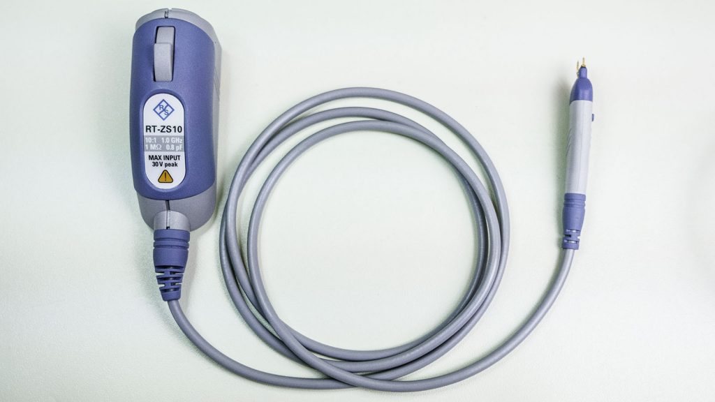
Single-ended active probes measure the signal with respect to ground. (The same way the passive probe works.) The RT-ZS10 1GHz active probe I have has 1 MΩ of impedance with 0.8 pF (that is 800 femtofarads!) of loading. Compared to a passive probe, that is ten (10) times less resistive loading but almost twelve (12) times less capacitive loading.
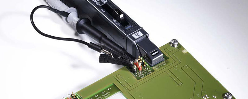
Let’s go back to the resistor-capacitor circuit model I mentioned earlier. A single-ended active probe is like a 1 MΩ resistor in parallel with your circuit along with 800 femtofarads of capacitance. You probably could not notice much difference between an active or passive on a DC rail. So here, I am measuring the Arduino Uno’s ceramic resonator.
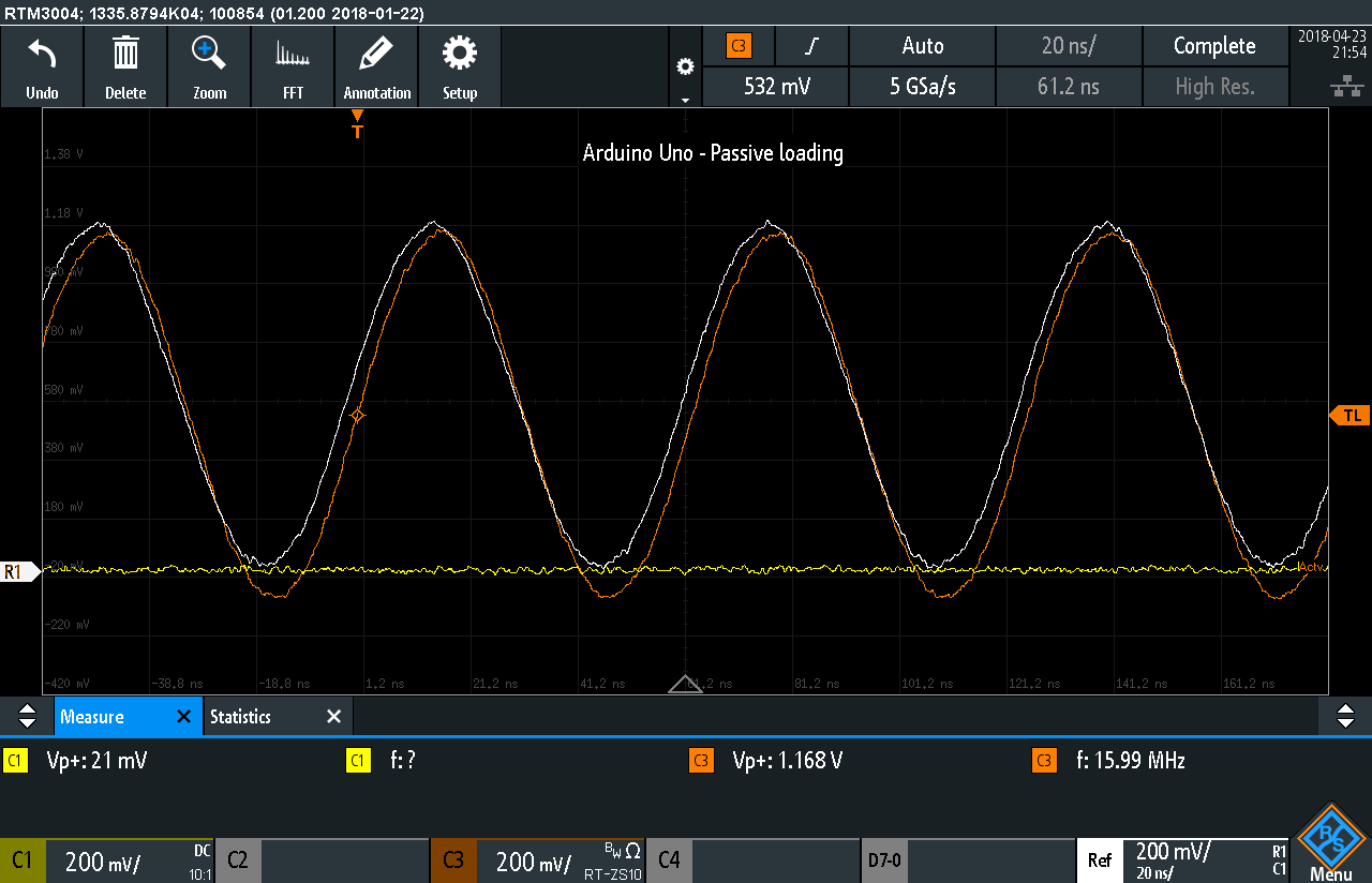
Channel 1 (yellow) is the active probe. Channel 3 (orange) is the passive probe. The white trace is a reference, or stored, waveform. I measured the same point with both probes as shown in the picture. The orange trace shows how the waveform changes by removing the passive probe. In this measurement, the loading effect is relatively minor. However, you can see how the high capacitive load of a passive probe could affect a sensitive circuit, like an oscillator.
Differential
Differential probes are also active, but different from single-ended. Instead of measuring a signal with respect to ground, two signals measure relative to each other. These probes operate very similar to an op-amp.
Differential probes are ideal for use with differential signals. (Obviously.) Examples might include technologies like SATA, PCI-Express, and USB. These communication standards use differential signaling.
It is possible to use two single-ended probes in place of a differential probe. On the oscilloscope, you will need to use a math function to subtract the two channels. This measurement has poor common-mode rejection compared to a true differential probe.
Differential probes have the same advantages of an active single-ended probe: high bandwidth and low loading. On the negative side, they tend to be expensive and do not have as much voltage range as a single-ended active probe.
High-Voltage Differential (Isolated) Probes
Making high voltage (>100 V) DC or AC measurements can be dangerous. The oscilloscope’s chassis ground connects to Earth ground. If the device under test is using a different ground reference, this can be a dangerous situation.
First, if there are different ground references, then the probe’s cable becomes the path to equalize them. When measuring low voltage DC, and relatively small currents, this equalization is essential. But when dealing with high power motors and power distribution networks, the difference can be destructive.
One way around this ground-loop problem is to remove the scope’s Earth tab. This modification will disconnect its chassis from Earth causing it’s “ground” reference to be the same as the circuit under test. DO NOT DO THIS METHOD. In a fault condition, YOU become the path to Earth—and in many cases only once.
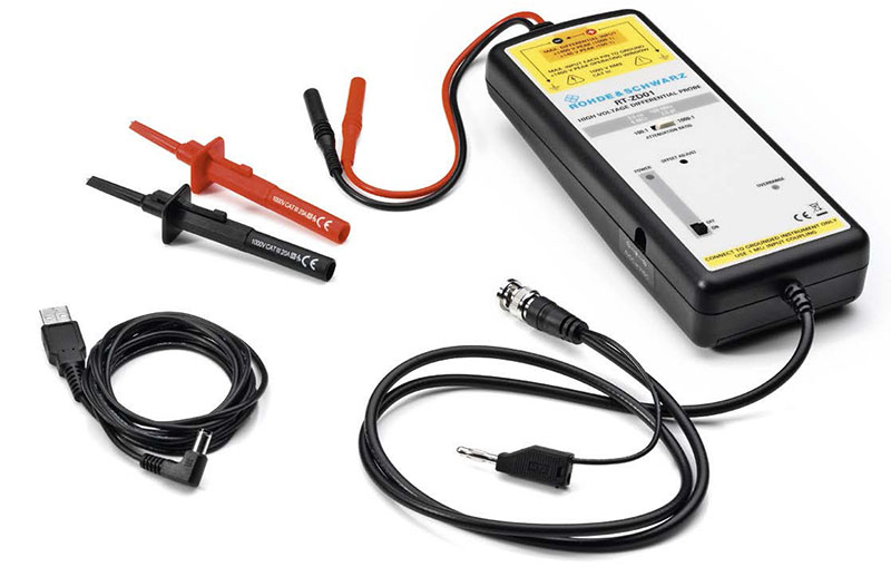
The safest way to make this measurement is with an isolated differential probe. The inputs isolate the probe from chassis ground (or Earth) making them suitable for high voltage applications. This isolation means it is safe to connect one of its inputs to the device’s ground. There is no path for leakage current to flow. This type of measuring is also called a “floating” measurement.
The bandwidth of high-voltage differential oscilloscope probes are limited to a few hundred megahertz. While working with high voltages is one reason, the other is a bit more subtle. To prevent arcing the inputs have an increased amount of physical separation. The more separation, the longer the current loop, which means less bandwidth.
While measuring a generator designed to connect to AC mains, this may not be a concern. However, a GaN or SiC inverter operates at higher frequencies.
When measuring high voltage AC (or high voltage DC) you need to take special precautions. Even if you are using a high-voltage differential probe or an isolated input or a battery powered scope, act as if you are not.
- Do not change connections in a powered circuit.
- Never use two hands when moving probes.
- And make sure someone else is around while you make your measurements.
Please, be careful when measuring lethal voltages.
Current Probes
Current probes measure current instead of voltage. Compared to a multimeter, you get a much better look at the power consumption of a modern digital device with an oscilloscope.
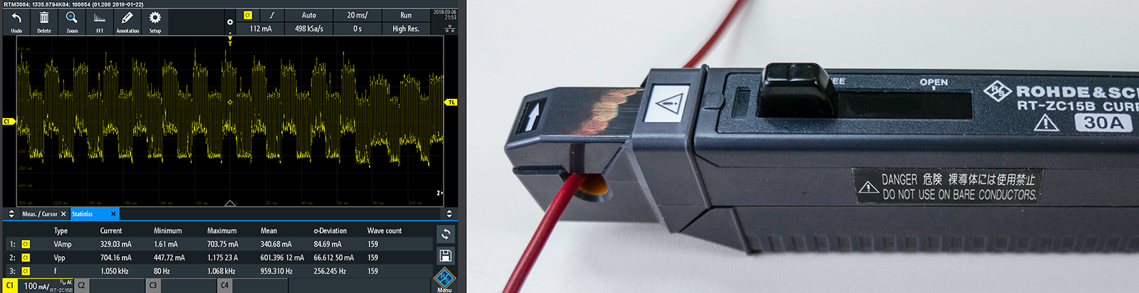
One caution when using current probes is that they are a hall-effect sensor. Which regarding measurement quality is excellent. However, there is a more significant propagation delay between when something happens at the probe tip relative to what shows up on screen.
If you buy a current probe, consider also acquiring a deskew fixture. This fixture will remove the propagation delay giving a more accurate view of your signals.
Conclusion
As I said at the start, this is not meant to be a comprehensive guide to scope probes. Instead, I wanted to make you aware of several different types that cover the most common measurements for an oscilloscope.


2 Comments
I always find current probes to be magical in that the current profile offers brand new insight into what’s going on in your system, very different from what voltage tells you.
Also, my old-school mentor calls active probes FET probes, it has stuck with me.
Wow. That just brought back a memory. I had a mentor 20 years ago who literally had a grey beard and work suspenders. He called them FET probes too.