Author

James Lewis

Browsing

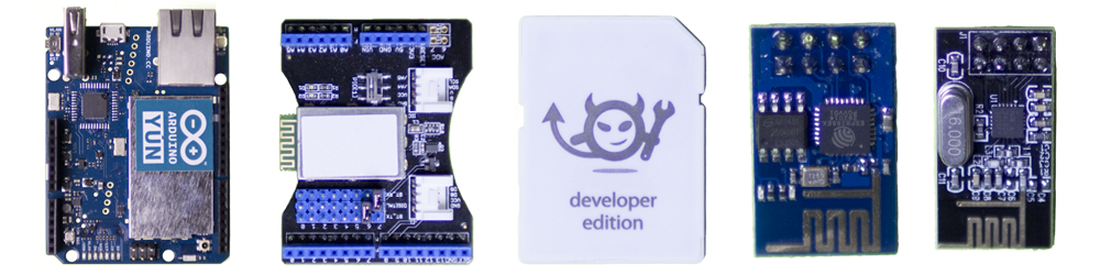
Your IoT project needs one of these wireless modules

Getting your project connected to the internet is relatively easy these days. Here are five off the shelf modules that will easily add wireless to your project.

Back when I was in school, I remember spending an entire semester making a RF amplifier board. In fact, I had to use a pencil eraser to remove oxidation on the copper traces to remove an unwanted oscillation, caused by the impedance mismatch of the oxidation on the copper traces. Talk about tough.

These days, adding WiFi or Bluetooth is as simple as adding one of the wireless modules available. Or if you are using an Arduino, skip the modules and just add a shield.

Keep reading for 5 different wireless modules to consider for your project.
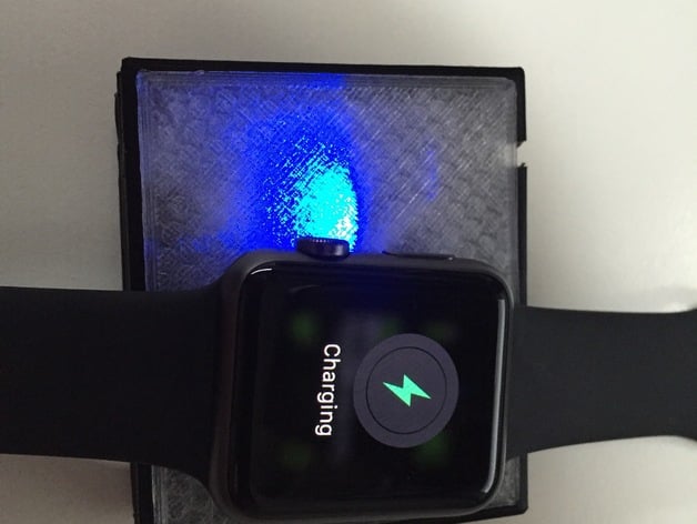
Apple Watch Charger on Thingiverse

Using an Adafruit Charger Board,  a cut-up magnetic Apple Watch Charger cable and some 3d printing, guypl has created a DIY battery-powered charger for the Apple Watch.

The cool thing about the design is that the 2000mAh battery he used, can be recharged with a standard micro USB cable. As someone who travels often, this setup is ideal for me. One less cable to carry and a self-contained charger for the Apple Watch.

Check out the full project on Thingiverse.


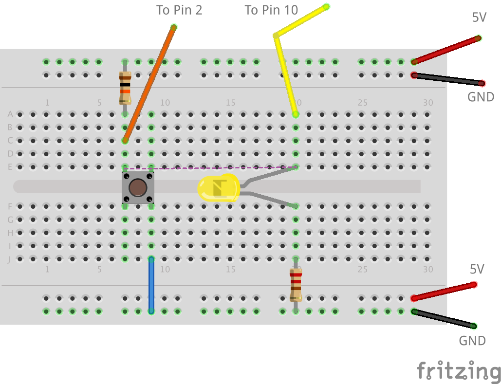
How to blink (or flash) a LED without delay() and detect button pushes

One of the limitations of the delay() function is that nothing else can really be done. This presents a problem when you want to flash a LED while waiting for a pushbutton to be pressed.

Flashing the LED with millis() and using a flag variable to find if the LED should be flashing solves this problem.

Consider this another example to my virtual millis() cookbook.

This code (below) should work with both Arduino (AVR) and Energia (supported boards), but to be honest, I haven’t had a chance to test it on my MSP430 yet.

Learning to a breadboard is critical when adding electronics to a project. A skill often overlooked is how to use breadboard jumper wires correctly. For example, when I breadboard a circuit I only use Red, Green, or Blue for positive voltages and Black for ground. Other colors, it depends on the functions of the wire. The idea is to keep it clear when I look at the board, what each wire is doing.

This video from Make is a great overview of how to develop a skill, or habit, around using breadboard jumper wires in your circuit.

For more information, there is a short writeup on their web site as well.

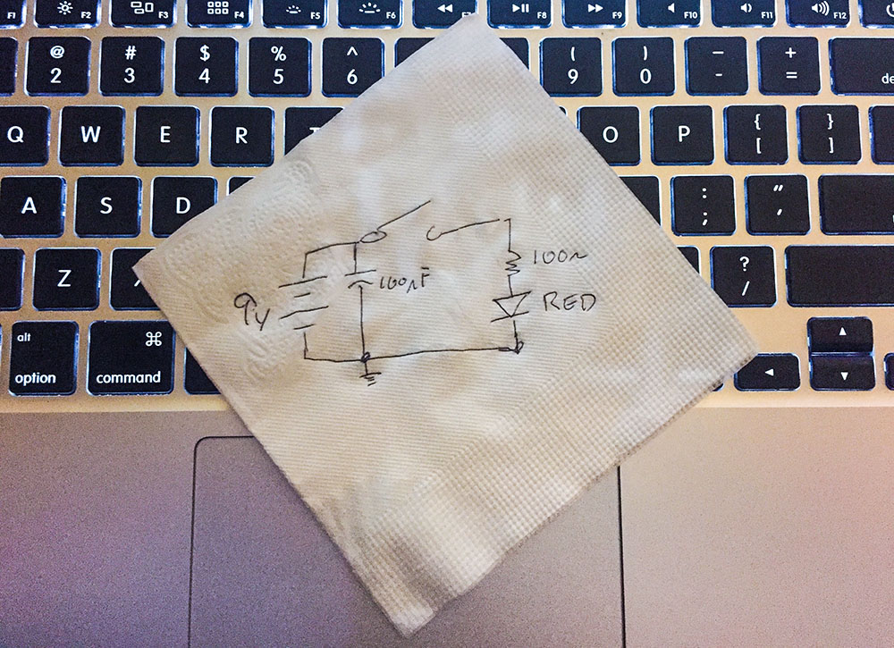
Engineers make a schematic to explain their circuits.

One time I was looking for a non-tourist pub in Japan. I asked someone for help. She said, “I’m sorry, but I do not speak good English. I will bring my friend, and she will draw you a map.” (Exact quote!) The map her friend drew, gave directions to a bar with a “Neon Yellow Sing.” She meant “sign.”

The map was the method we used to communicate with each other, even though we didn’t both speak English. With this crude but useful map, I could find my next drinking place destination.

Schematics are the same as this map. Even if you don’t speak the same language, you can communicate how a circuit works when you make a schematic.

Use one of these five tools, when you need to a document a circuit or when you need to ask for help.