Soldering every circuit you build probably isn’t practical. At some point you are probably going to want to use some type of temporary method to connect different components together. One of the popular methods is using a breadboard. This simple (and cool) looking device only needs a few instructions before you can begin
Layout of a Breadboard
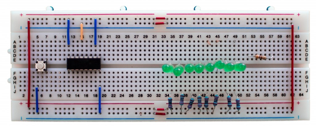
There are various colors, shapes, and sizes that breadboards come in. However, they all generally look about the same and have the same basic functionality. The board shown in Picture 1 is a pretty common “medium” sized breadboard.
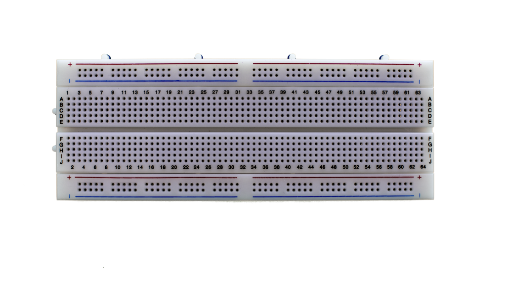
This particular breadboard has 4 “bus strips” sections, which are used for power and two big blocks of “terminal strips” where you’ll place components and jumper wires. Sometimes you can find this style mounted to a metal (or sometimes plastic) plate with banana plugs to accommodate connection to a bench power supply. You can also find configurations with several of these “blocks” on one single board. In fact, the one pictured here can be connected to other boards to form a larger work area.
Bus Strips (aka Power Rails)
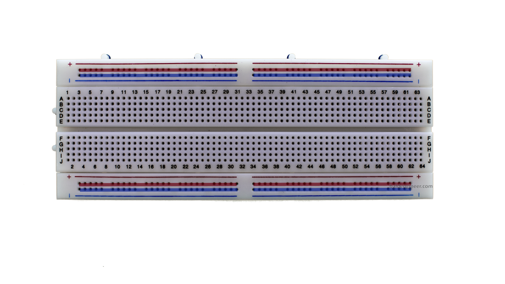
Looking at Picture 2 each of the bus “strips” are separated from each other into four groups. Not all boards will work this way, but most with a “break” between the rows are disconnected. Within the groups the rails are connected. In this case, this board shows a silkscreen of which holes are connected together, I’ve overlaid an additional graphic to highlight. The advantage to this design is that you can have 4 different power rails (well technically up to 8) on a single breadboard. Practically, this is rarely the case. At most you might have +3.3V and +5V, but your mileage will vary.
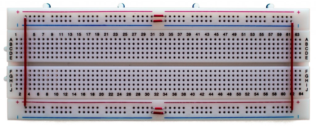
Generally I will connect all of the grounds together since it is rare I have a circuit with different grounds. Unless I am working with more than 1 VCC (5V), I keep all of the positive rails connected together with little jumper wires. Picture 3 is what my breadboards generally look like. If the breadboard has colors for the rails, I don’t worry about wire colors. However, if it doesn’t have color lines, I will carefully use Red for Positive and Green or Black for Negative.
Terminal Strips (aka Component Area)
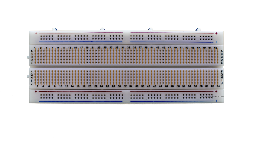
The majority of a electronic bread board is dedicated to a place to put parts. Because hey, if you can’t put parts down you aren’t going to do anything interesting, right? Each “Column” is connected together and typically you’ll see 5-6 holes in a column. As Picture 4 shows, the columns on either side of the ditch in the middle are not connected together. The separation of these two sections is generally enough so that a DIP chip will fit in them perfectly.
Row and Column Labels
Generally there will be some labels for the rows and columns of the breadboard. On higher quality boards these letters will be silkscreened for better readability. Just a personal note, I hardly ever reference these designators. You could, for example, use them to keep track of pins on an IC. However, I find it less error prone to just count the pins on an IC than do offset math.
Limitations
There are a couple of limitations you should be aware of when using a breadboard for your circuits
Parasitics
Inside of each hold are tiny little clips. This adds some parasitics (extra stuff you don’t want) like capacitance, inductance, and resistance. The DC resistance tends to be low, although slightly more than just plain wires. The capacitance and inductance, however, means that high-frequency stuff isn’t going to work so well. While it is common for people to get an Arduino circuit to run on a breadboard, the 16MHz the Arduino runs at is probably the limit of decent performance. Even then, you would need a relatively new board that is in good shape. Because…
Unreliable Connections
Over time, the little clips and springs that make up the connections inside the breadboard wear out. If you push a wire in too far (and too hard) you may make unintended connections. As you change connections around, you might bump a wire or resistor sticking up which may make (or break) a connection.
Tip: After 2 years of moderate use, I throw a breadboard away.
Limited Power
Most bread boards can handle up to 1A through their connections at digital-level voltages (5V and below). Even so, I would really try to limit current through any breadboard to the 500mA range.
SMD Compatibility
Obviously if a part doesn’t have wires or leads, you aren’t going be able to plug it into a breadboard. So if you’ve got some surface mount components, you’ll need to get breakout boards to attach the surface mount components to first, before you can plug them into a breadboard.
Conclusion
If you are playing with electronics, eventually you’ll be using a breadboard. The key to remember is that the “component” area is columns connected together while the “power rails” are rows connected together. If in doubt, check with a ohmmeter to see if two holes have a connection.




7 Comments
I know this will sound silly, but everyone was a beginner once, right?
I have components with just plain wire ends, not the solid ends of a jumper wire. Any ideas on how to get a secure fit?
Hope someone gets a laugh out this, really,
–Al–
[email protected]
Good time to learn how to carefully solder the tip of the wire into a single point. 🙂
Hi, what brand of breadboard is pictured above? It looks to be of better quality than what I’ve seen online. Thank you!
Good question. Frankly, I do not remember. I probably got that one from a supplier like Adafruit or Sparkfun.
Pingback: baldengineer | 6 Simple Mistakes Electronics Beginners Make
i appreciate the way you’ve broken this down. as a newbie to the world of arduino, having explanations, images and examples laid out like this is far preferred. (and one of the very reasons i’ve subscribed to your feed.
ps, thank you for explaining millis (replacing delay() ) i’ve been staying up late trying to figure out how to multitask my arduino automated chicken coop (yes, i’m completely over-doing it with too many amenities) and your tutorial headed me in the right direction.
cheers,
//d
ps, your photo looking up at your newlsetter section… brilliant. =)
Dave,
Thanks for the feedback.
millis() is great when you have “too much” going on. In fact, if you’re clever you can add some checks to make sure that processes aren’t taking too long to get executed. If they are, then you can throw a flag. For example, if you say “execute if 1000ms have passed” then immediately check to see if more than 1250ms passed, if so, throw a flag.
Cheers