Tag

arduino

Browsing

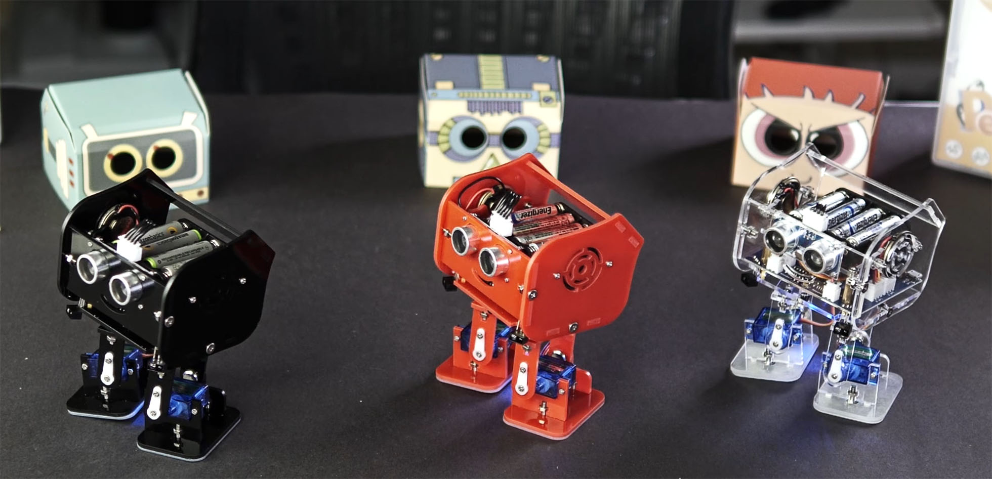
Recently I received three packages from Elegoo Industries. They are a company based in Shenzhen China. Before those packages, I noticed their name several times on various electronics kits on Amazon. They asked me if I’d help them with a video that shows how to assemble their latest creation: Penguin Bot.

There is not much point in sharing that video with you unless you’ve purchased one. So instead, here is my review, or hands-on, of the kit. I will, however, show you a short Instagram video I made to show off Penguin Bot’s cuteness.

https://www.instagram.com/p/Bn0MbnzHCYj

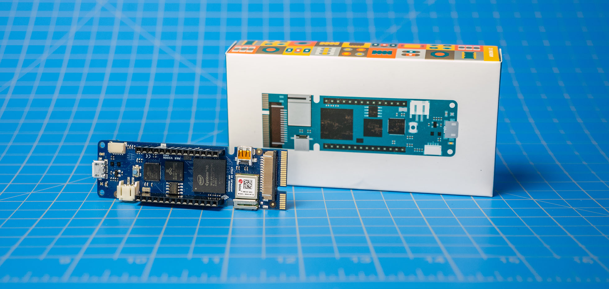
Earlier this week, I looked at the Arduino MKR Vidor 4000 during an AddOhms live stream. My goal was to understand the Vidor better. It is the new FPGA-based Arduino which started shipping this month. It runs about $60. You can learn more at the Vidor Product Page on the Arduino website.

In this post, I briefly touch on the difference between an FPGA and a microcontroller. Then I walk you around the MKR Vidor 4000’s board. Using one of the examples, I talk a bit about how the various chips communicate with each other. This section also highlights what makes the Arduino FPGA board different from other development boards. Lastly, I answer “should you buy an Arduino MKR Vidor 4000?”

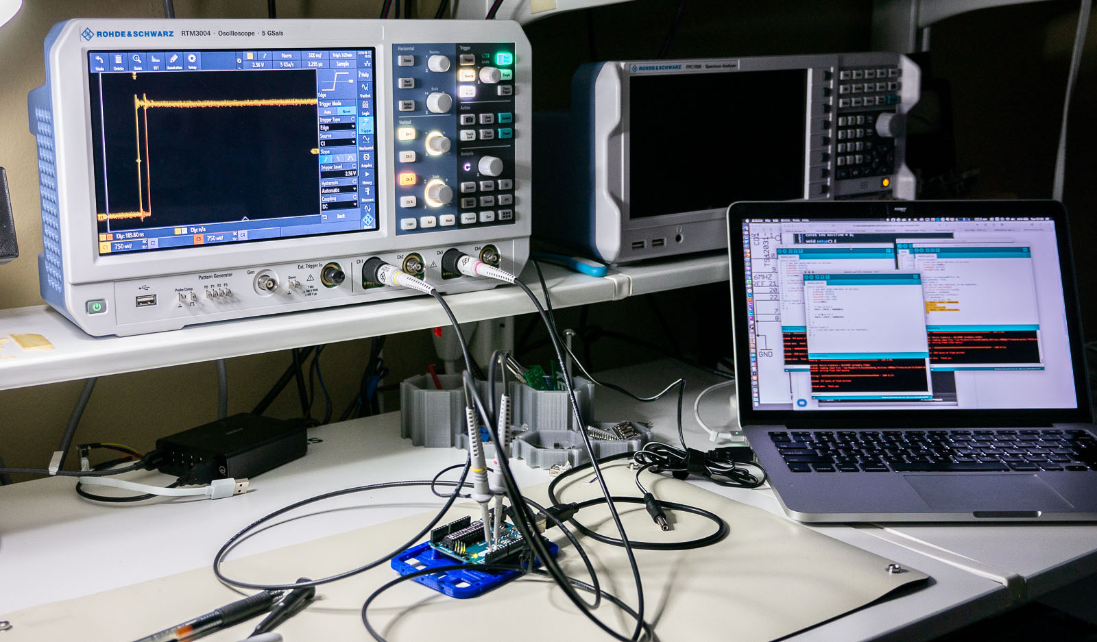
One of the best ways to learn how to use a new piece of test equipment is to use it. Sounds easy, right? The problem is, sometimes when you are in the middle of troubleshooting your circuit, figuring out what the knobs on your scope do is an immense frustration. Use these 6 oscilloscope measurements, and just an Arduino Uno, to learn how to use a new or unfamiliar digital scope.

This tutorial is not a step-by-step guide on how to make each of these measurements on a particular scope. Instead, it is a general explanation on how to setup the Arduino and a screenshot to help identify if you set up your scope correctly. I reference the R&S RTM3004. However, practically any two (or more) digital channel oscilloscope should work.

Between each measurement, I highly recommend using your scope’s default setup (or autoscale) before proceeding to the next one!

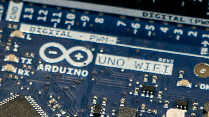
Arduino announced several new products at the 2018 Bay Area Maker Faire. One of those products is the Uno WiFi Rev 2. (Check out this post for an introduction to the MKR Vidor 4000, an FPGA-based board. You can read their official announcement here. This new Uno board represents a significant upgrade for the 8-bit family of Arduino boards. However, I do have a few reservations.

Arduino Uno WiFi Rev 2

Starting off, I am not happy with the name. It is too long. For that reason, I am going to keep using the full name in this post to demonstrate why I don’t like it. Another reason I’m grumpy it that new microprocessor makes it incompatible with 328p code. That said,  sketches (and libraries) using only the Arduino library will (likely) work fine. Anything that uses registers, like direct port manipulation, will have issues. Just like moving to any other architecture supported by the IDE. However, because it has the name “Uno,” many users will be tripped up by incompatibilities. 

Keeping the name “Uno” was only there for marketing reasons. The form factor is the traditional Arduino Uno style. Which begs the question, can we retire that massive USB connector yet? 

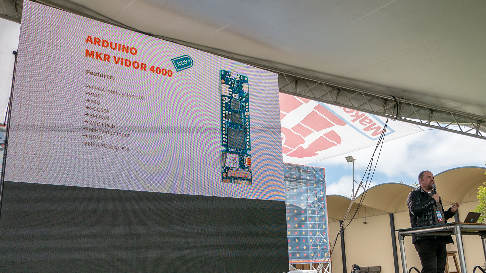
Arduino announced several new products at the 2018 Bay Area Maker Faire. One of those products is the MKR Vidor 4000, an FPGA-based board. You can read their official announcement here. (Over here is a write-up on the new Uno WiFi Rev 2.) The goal of the MKR Vidor is to make FPGA accessible to makers and innovators. It represents a new shift in hardware focus for the Arduino team.

An FPGA is a Field Programmable Gate Array. In other words, it is reconfigurable hardware. Unlike a microcontroller, an FPGA is not running software. Instead, its gate array changes configurations for a specific task.

The example I like to think about is a rotary encoder. You might find one on the spindle of a motor. As the motor spins, an IR sensor detects slits in the encoder to track speed and direction. In a microcontroller based system, you might use an interrupt to monitor the IR sensor. Even though interrupts can respond quickly, there is still a chance of missing a pulse. Plus, the rest of the microcontroller has to wait while the interrupt is handled. In an FPGA, however, you would build a hardware counter with the pulse driving the counter’s clock input. This counting happens independently of whatever else the FPGA is doing.