A couple of weeks ago I posted an EAGLE Tutorial on creating Ground Planes. That tutorial has now been updated with the above YouTube video showing the steps. Let me know if there’s anything else I can do to make it more clear.
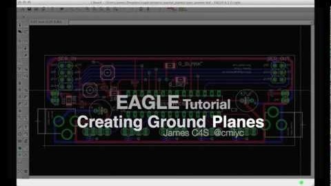

A couple of weeks ago I posted an EAGLE Tutorial on creating Ground Planes. That tutorial has now been updated with the above YouTube video showing the steps. Let me know if there’s anything else I can do to make it more clear.
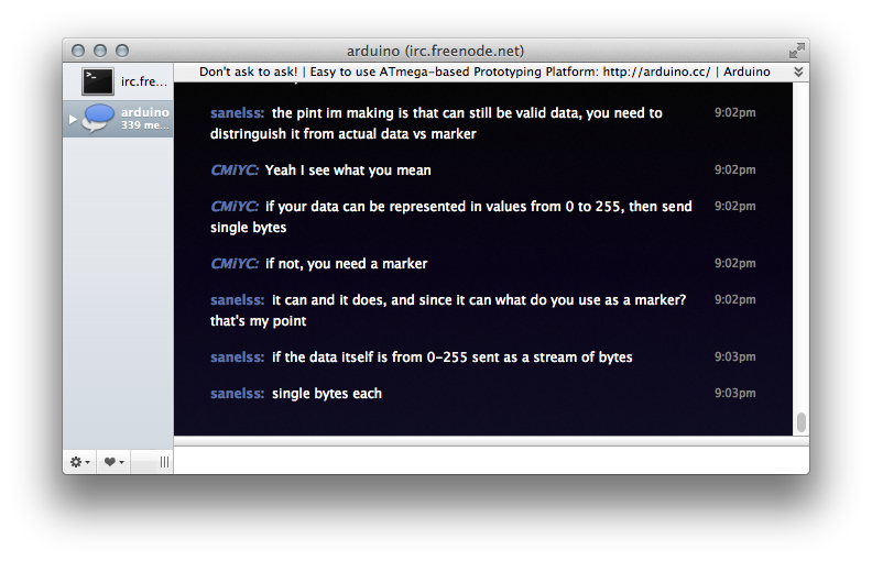
While the Arduino Project Team provides their official Arduino forums, sometimes real-time help is just a bit better. When that is the case, I encourage you to visit the freenode.net IRC channel, #arduino. While as of today it is not an official channel, there are a number of great people available to help.
You can find me under the nick “baldengineer”, big surprise, I know. Others like kline, Yoston and pwillard are also excellent people to ping with questions.
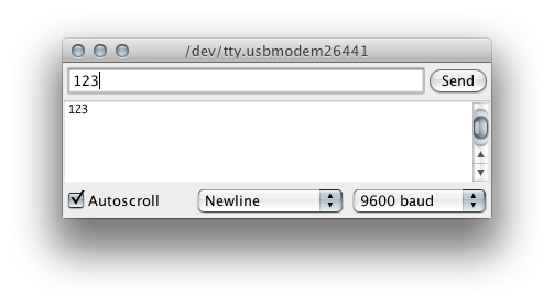
When Serial data is transmitted to an Arduino, it is sent one byte at a time. Even though you might type “123” in the Serial Monitor, that’s not quite what is sent. Instead the bytes “1” then “2” then “3” are sent. Once received into a buffer on the Arduino, these individual bytes need to be reassembled into something useful.
Based on a question from Andrew on the initial Multitasking with millis() tutorial, this example shows how to create a Police-Light like strobe effect. The following code uses no calls to delay().
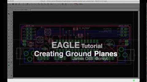
Creating PCBs in Eagle is a straight-forward process once you understand how EAGLE works. In fact, most users can get up to speed enough to draw a Schematic and then layout a simple PCB. Making the connections between components is not only fun but can be a form of artwork.
Often overlooked is how much space is left wide open. For example, a board might look like this:
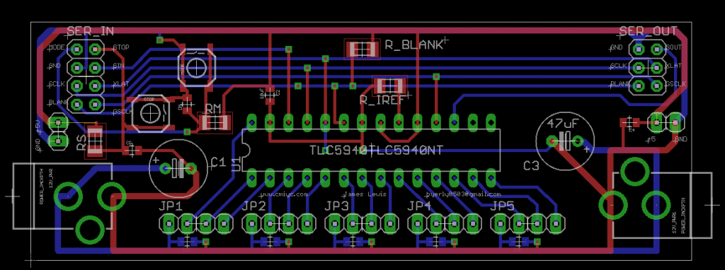
The area in black will have no copper. For circuits that don’t require a ground plane, this may not be an issue. However, it rarely hurts to fill in empty area with a ground plane. EAGLE makes it very easy to do this, after your circuit design is complete.