
 When using this current sensor I ran into an unexpected issue. It’s fast, and it’s precise. (Isn’t that a good thing?) The way it works is by measuring the voltage drop across a precision shunt resistor that the load current flows through. Using Ohm’s Law, it comes up with a current measurement. However, it is much faster than I expected and was providing (nearly) instant answers. So each time I checked the sensor, I got a seemingly random value.
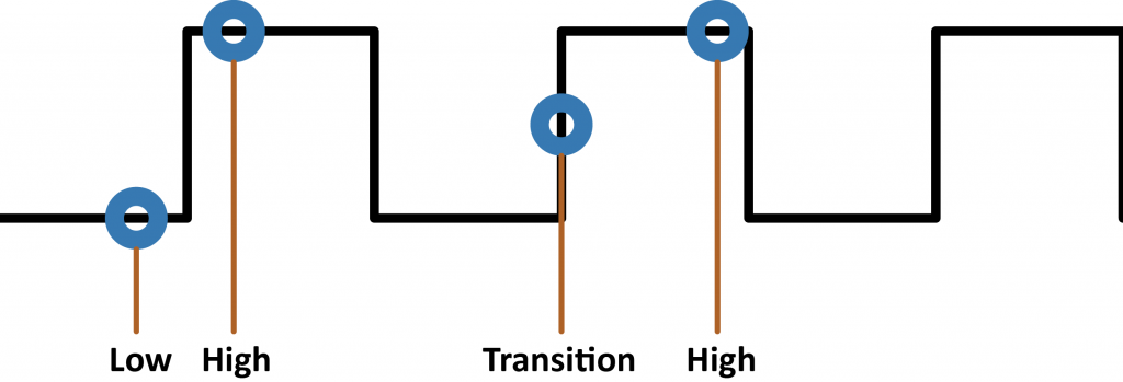
The problem is the value depended on when I sampled the PWM waveform, like illustrated below. I’d get the “high” current, “low” current (none), or a transition. The “high” current was useful, but none of the other values.
When using this current sensor I ran into an unexpected issue. It’s fast, and it’s precise. (Isn’t that a good thing?) The way it works is by measuring the voltage drop across a precision shunt resistor that the load current flows through. Using Ohm’s Law, it comes up with a current measurement. However, it is much faster than I expected and was providing (nearly) instant answers. So each time I checked the sensor, I got a seemingly random value.
The problem is the value depended on when I sampled the PWM waveform, like illustrated below. I’d get the “high” current, “low” current (none), or a transition. The “high” current was useful, but none of the other values.
 Using a simple averaging algorithm I sometimes got stable values, but not by much. Plus, it was taking up hundreds of bytes of RAM just to get an idea of the RMS current used in my design. I needed that so I could more easily calculate power usage.
That’s when I learned about Modified Moving Average or MMA. This simple algorithm uses only a few bytes of RAM and is more accurate than a simple averaging algorithm. Plus if you’re using a slower processor, like the Uno’s ATmega328p this method uses much less floating point. (This article explains other types of moving averages.)
Using a simple averaging algorithm I sometimes got stable values, but not by much. Plus, it was taking up hundreds of bytes of RAM just to get an idea of the RMS current used in my design. I needed that so I could more easily calculate power usage.
That’s when I learned about Modified Moving Average or MMA. This simple algorithm uses only a few bytes of RAM and is more accurate than a simple averaging algorithm. Plus if you’re using a slower processor, like the Uno’s ATmega328p this method uses much less floating point. (This article explains other types of moving averages.)
Algorithm to measure PWM current
When using MMA, you only need to store three values: “Moving Average Sum,” “Moving Average,” and the number of samples. Obviously, the number of samples can be a constant, saving a byte or two of memory.Moving Average Sum
Instead of collecting N samples and keep a history of samples, or measuring N samples all at once (a horrible idea, btw), the Moving Average Sum is just that. The previous measurements summed together, with a slight twice.Moving Average
After a new sample is added to the modified moving average, a new average value is calculated. This math is the most time-consuming step since division is involved. (If you didn’t know, most processors don’t know how to divide.)How MMA Works
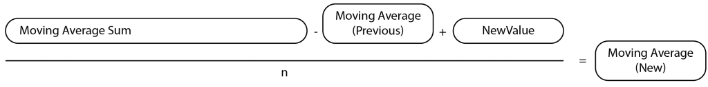 The algorithm works like this: Subtract the previous average from the sum. Get a new sample and add that to the sum, replacing the “average” you just removed. Then, recalculate the average.
The idea is that since you are removing, effectively, 1 sample and then adding a new sample in, it allows the average to shift in time.
This averaging will smooth out fluctuations while providing an accurate average, all while using only 4-6 bytes of RAM. The best part is that if you increase the number of samples used for the sum, neither the RAM nor the calculation time changes.
The algorithm works like this: Subtract the previous average from the sum. Get a new sample and add that to the sum, replacing the “average” you just removed. Then, recalculate the average.
The idea is that since you are removing, effectively, 1 sample and then adding a new sample in, it allows the average to shift in time.
This averaging will smooth out fluctuations while providing an accurate average, all while using only 4-6 bytes of RAM. The best part is that if you increase the number of samples used for the sum, neither the RAM nor the calculation time changes.
MMA Code
During each iteration of the main loop, my RGB LED IoT controller samples a new value and updates the moving average. Before I moved to the ESP8266, this code took about 56us to execute on an Uno. That speed is fast enough; it has little impact on the program’s performance.
//inside of loop()
 float currentCurrentValue = ina219.getCurrent_mA();
 if (currentCurrentValue > maxCurrent)
 maxCurrent = currentCurrentValue;

 movingAverageSum -= movingAverage;
 movingAverageSum += currentCurrentValue;
 movingAverage = movingAverageSum / N;
Comparing Simple Average to MMA
I have prepared two Arduino projects to compare a Simple Average to the Modified Moving Average. You can download the Simple Average Example Here and grab the MMA example from both. For the hardware, you can use almost any Arduino. You just need PWM and Analog In pins. (Be careful on ESP8266s, since the maximum Analog In is only 1 volt.) In my test, I used an Uno and inserted a wire from digital pin 5 to analog pin A0.
// Modified Moving Average for PWM Curerent or PWM Voltage
// by James Lewis
// www.baldengineer.com/mma
//
// Connect a wire between pin 5 (pwmPin) and analog 0 (analogPin)
// Open the serial monitor. Send the + and - characters to change
// the speed. (you can type in multiples like '+++' to change quickly)
//
// The "average" voltage valued display is the PWM average
// uses 244 bytes of RAM versus 442 bytes of RAM for 100 averages
// calcultes in about 56us versus 1068us

// Pins
const byte pwmPin = 5;
const byte analogPin = A0;

// Let's compare an average of 100
const byte averageCount = 100;

// So we can change the PWM value
int PWMvalue = 128; //~50% Duty

// Variables for the Modified Moving Average
float movingAverage;
float movingAverageSum;

// Timer variables
unsigned long previousMillis = 0;
unsigned int printInterval = 500;
unsigned long startTime = 0;
unsigned long stopTime = 0;

void setup() {
  // put your setup code here, to run once:
  Serial.begin(9600);
  pinMode(analogPin, INPUT); // not necessary, for FYI
  pinMode(pwmPin, OUTPUT); // not neceessary, for FYI

  // Start the PWM waveform
  analogWrite(pwmPin, PWMvalue); // ~50% Duty Cycle

  // Pre-load MMA
  for (int x=0; x < averageCount; x++)
    movingAverageSum = movingAverageSum + analogRead(analogPin);

   // Calculate inital average
   movingAverage = movingAverageSum / averageCount;
}

void loop() {
  // check for serial control
  handleSerial();


  // each interation of loop, update moving average
  // Get a new sample
  unsigned int currentValue = analogRead(analogPin);

  startTime = micros();
  // Remove previous movingAverage from the sum
  movingAverageSum = movingAverageSum - movingAverage;
  // Replace it with the current sample
  movingAverageSum = movingAverageSum + currentValue;
  // Recalculate movingAverage
  movingAverage = movingAverageSum / averageCount;
  stopTime = micros();

  if (millis() - previousMillis >= printInterval) {
    Serial.print(F("currentValue: "));
    Serial.println(currentValue);
    Serial.print(F("PWM Value: "));
    Serial.println(PWMvalue);
    Serial.print(F("Moving Average: "));
    Serial.println(movingAverage);
    Serial.print("Calculation time: ");
    Serial.print(stopTime - startTime);
    Serial.println(" us");
    Serial.println();
    Serial.flush();

    // reset the millis clock
    previousMillis = millis();

  }

}

void handleSerial() {
  // we only care about two characters to change the pwm
  if (Serial.available() > 0) {
    switch (Serial.read()) {
      case '+':
        PWMvalue = PWMvalue + 32;
        if (PWMvalue >= 255)
          PWMvalue = 255;
      break;
      case '-':
        PWMvalue = PWMvalue - 32;
        if (PWMvalue <= 0)
          PWMvalue = 0;
      break;
    }
    analogWrite(pwmPin, PWMvalue);
  }
}
currentValue: 1022
PWM Value: 255
Moving Average: 1022.05
Calculation time: 56 us

currentValue: 1022
PWM Value: 159
Moving Average: 595.21
Calculation time: 56 us
Conclusion
Whether you are measuring PWM Current or PWM Voltage, using an MMA can give you the average output value. When calculating power, this is helpful because you don’t need to include time in your math. When looking at a voltage, you can get an idea of the effective voltage for a load like a LED or Motor.Industry Notes
Check out this application note from Intersil on “Sensing Elements for Current Measurements.” Cool overview of different technologies for current measurements. (In my example here, I am using a Shunt Resistor.)The only examples I found for this algorithm were financial. What other maths can be helpful in everyday microcontroller projects?


8 Comments
It might be worthwhile to put units on your prints. `currentValue: 1022 mA` and `Moving Average: 595.21 mA` otherwise A great read.
Your procedure for measuring PWM current is wrong and insensitive for changing load currents. You could get any MMA number between 0 and max. current depending upon co-incidence of sampling instants and state of PWM output (ie low or high). To prove this, consider that PWM current waveform is repetitive (for constant duty cycle) and your sampling period is fixed. Measurement accuracy now depends upon their co-incidence. Also, your moving average graph is wrong because PWM amplitude is constant (except for capacitive/ inductive loads).
To accurately measure PWM current as an average DC value, you need to know PWM pulse frequency and no. of output states. For Arduino Uno, these PWM factors are approx. 500Hz (ie 2ms period) and 256 states. Now sample the current at 7.81us ( 2ms/ 256) time interval for 256 measurements (there is no need to synchronise sampling instant to PWM output); sum the sampled values (0-1023 for Arduino Uno) as long ints. After 256 measurements:
1 multiply sum by current conversion factor* to get ‘ summed current’ number, (*= Amps/ 1024);
2 divide ‘ summed current’ by 256 to get average DC current which accurately equates to heating effect.
Repeat above procedure for each current measurement as required. Measurement accuracy for capacitive/ inductive loads will be good due to symmetry.
The Uno can achieve the ADC sampling requirements provided the ADC prescaler is set at 2 or 4 cycles. Accepting decreased accuracy, you can reduce number of samples from 256.
Yes, if you know all the details you listed AND your program can guarantee a specified sample rate, then there is a better method to calculate the average current. This example was for when either of those is not the case. In which, a modified moving average is the way to go.
Good writing. Just a comment : what about using averageCount as 2^n value e.g. ( 16, 32, 4 , 128 , 256 ) and replace the DIV with SHIFT operation value = value >> averageCount . That might be faster
I think that will work great for Integers. However, I don’t think it’ll work for float (decimals).
A Kalman filter converges faster, especially for a changing signal with noise. avionics workhorse. makes me want to code too & put it across as simply. meanwhile, this’ll help. brace for a few other languages and some noise, while following all the leaves of the page here.
http://dsp.stackexchange.com/questions/21598/when-is-a-kalman-filter-different-from-a-moving-average
Hi James, A good article and very timely for me since I am currently dealing with a noisy signal from an ACS712 current sensor. Maybe the INA219 would be better for me. However i have a couple of suggestions for you to consider.
a) it is not necessary to use floating point variables. Using integers would reduce the computation burden on the microcontroller processor.
b) if the averaging length “N” is chosen as a power of 2 (eg 4 or 8 etc) the division process becomes a simple shift which is also very easy for the microcontroller processor.
Those are the main points, which I expand on below, at the risk of becoming tedious.
I find it easier to understand the MMA if the equation is written like this:
MAt = MAt-1 * (n-1)/n + At / n
where MAt is the moving average at time t, MAt-1 is the moving average at time t-1 (ie the previous measurement) and At is the measured result at time t. n is the averaging length.
That is, the new moving average is made up of (1/n) of the new value, and (n-1)/n of the previous value.
Your calculation does this equation in two steps:
MASt = n * MAt = MASt-1 – MAt-1 + At — step 1; keep MASt for next time
MAt = MASt / n — step 2, end result
This calculation can be done using integers rather than floating point. The INA219 generates its results for both current and voltage as 16 bit integers (with maximum 12 bit accuracy due to ADC limitations).
The calculation can be done with integers without loss of accuracy so long as MAS (MovingAveragSum) is stored as a long integer (32 bits). The code lines are identical to the ones in your photo under “MMA code” in your article, except that in line 2 the variable currentCurrentValue can be int rather than float. Previously movingAverageSum needs to be declared as long rather than float.
As to performance, it is easy to do a quick spreadsheet that demonstrates how this algorithm responds to various inputs. For example, in a new tab I set up the following:
Column A: rows 2 to 20 all 0, rows 21 to 60 all 1.
Column B: row 1 = 8 (n = averaging length)
row 2 = cell A2 (starting value)
rows 3 = =B2*(B$1-1)/B$1+A3/B$1 (this is the first equation I gave above)
column B rows 4 to 60 – propagated by copy from row 3.
Then select A2 to B60 and make a chart – a simple line chart seems to work well.
You can put a sample of your real world data into column 1 to see what different averaging length values achieve.
With an averaging length of 8 and a 0 to 1 step function, the moving average gets to 90% of the new value in row 38 which is after 18 iterations, and to 99% in row 55 which is after 35 iterations.
Keep up the good work.
Regards,
Keith
Hi Jim, as a non-engineer I really appreciate your videos – they inform and are just the right speed to retain the interest, thank you! Keep up the quality content!!!!
I too recently came across a similar problem with trying to measure the AC amplitude coming out of a current sensor chip for a pic run automation project. The code I used is below. Other useful algorithms for pic/duinos would be efficient RNG. If you have any thoughts on a decent single digit RNG that is uber small in size and does not require large libs, please let me know 🙂 I could really use on for a tiny 10 series pic project.
[arduino firstline=””]
// Variable Declaration
int AN3_AD_IN_110 = 0; // variable to hold value of A/D input from U2 Allegro chip, 110v line.
int AN2_AD_IN_220 = 0; // ” from U3 Allegro chip, 220v line.
// This signal is baseline of 2.5VDC with a 0-2.5VAC signal riding on top.
int max110 = 511, min110 = 511,
max220 = 511, min220 = 511; // variables for min/max comparisons on both channels 110/220
int peak110 = 0, peak220 = 0; // Hold temp values to compare ADC against
int count = 0;
while (1)
{
while (count = max110) // check for 511 (1/2 Vcc) or greater
{
max110 = AN3_AD_IN_110; // set variable 110max to 511 or greater
}
if (AN3_AD_IN_110 = max220) // check for 511 (1/2 Vcc) or greater
{
max220 = AN2_AD_IN_220; // set variable max to 511 or greater
}
if (AN2_AD_IN_220 = 120) || (peak220 >= 230)) // control statement – if peak value is above thresholds then proceed
// 110V threshold is about 1.9A, 220V about 3.8A
{
__delay_ms(2000); // 2 second delay before turning on
GPIO0 = 1; // set GP0 high to turn on relay
}
if ((peak110 <= 60) && (peak220 <= 60))
{
__delay_ms(3000);
GPIO0 = 0;
}
count = 0; // reset count variable to zero for next go around
min110 = 511; // reset variable
max110 = 511; // reset variable
min220 = 511;
max220 = 511;
}
}
[/arduino]