Category

Arduino

Category

As a kid, I got the book “Upgrading and Repairing PCs.” (Now in its 22nd edition.) It was the first book to explain to me the PC architecture. I considered, how were there so few pins on an AT-style keyboard connector when there were 101 keys on the keyboard? That is when I first learned about the keyboard matrix.

Intel_P8049_AH_controller
Original image from Deskthority Wiki. (Edited image is shown.)

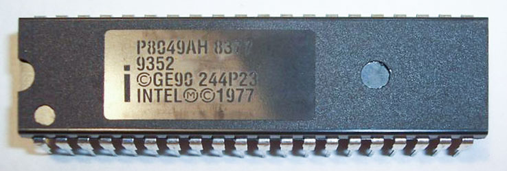
The keyboard matrix itself did not amaze me, but instead the idea there was an entirely separate 8-bit microcontroller inside of the keyboard. Early keyboards may have used the P8049AH, which, there is still some stock available to purchase. I was fascinated with the idea an entire computer was necessary to run the keyboard, to use my “real” computer. Why did it take something as complicated as a microcontroller?

A question came up on IRC regarding how to PWM a 3-pin PC fan with an Arduino using analogWrite(). Controlling the fan was seemingly straightforward. The problem was that the hall effect sensor, or TACH signal, was incredibly noisy. The noise made it impossible to measure the fan’s rotation. Working through the question, I found three issues to tackle:

  1. You need to use a PNP transistor
  2. Filter capacitors help
  3. Create a non-blocking RPM measurement (with millis())

This post addresses all three issues regarding how to PWM a 3-pin PC fan with an Arduino.

Previously I looked at the hardware needed to build a Raspberry Pi soft power supply. This week I’m looking the state machine for the microcontroller. Why is such a complicated circuit necessary? I am replacing a Super Famicom (SNES) motherboard with the Pi. The trick is, I want to use the original power switch to turn the Pi on and off.

This requirement presents a problem. When the switch goes into the “OFF” position, power needs to stay on long enough for the Pi to properly shutdown. So the switch itself can’t provide power to the Pi directly. With minor changes, the code in this state machine could be made to work with push buttons as well. If I add that feature in the future, I’ll update the code on the RPSPC GitHub project.

Before continuing with the state machine, first I need to thank all the mailing list members. You guys really rock. When I asked for state machine diagraming tool suggestions, you guys sent me enough options for an entire (future) post to compare them. 

To detect a short and long button press using millis can give your project more functionality without adding more buttons. In this line-by-line example, I show how to react to a user pressing a button for a short period (100ms) or a long period (over 500ms). My example changes the blink rate of an LED on short presses. A long button press turns off the LED.

In the code, I make use of a struct so that a single variable can be used to track multiple parameters. The benefit of this method is that adding multiple buttons is easy. You could create an array of these tyepdef’d variables.

Download At GitHub
The Arduino serial monitor is usable when you want to watch data from an Arduino. However, it does not have a built-in method for saving the data. Here are some ideas if you want to build an Arduino data logger with or without a PC.

Important note on Arduino Data Logger examples

With all of these examples, please remember that whenever you open the Arduino’s serial port, the board will reset. So if your log file shows “Initializing SD card…” with a few data lines in between, it is because there is a reset happening.

Initializing SD card…initialized.
Temp: 34, Time: 03:24:44
Temp: 33, Time: 03:24:45
Temp: 34, Time: 03:24:46
Tem

Initializing SD card…initialized.
Temp: 34, Time: 03:24:50
Temp: 34, Time: 03:24:51
Temp: 33, Time: 03:24:52
Temp: 34, Time: 03:24:53
In that code you can see data logging started and then restarted. What happened is that after programming, the board starts logging. Then when you open the Serial Monitor, the data logger restarts. To solve this issue, either disable auto-reset, add a 3-4 second delay at the start of setup(), wait for a character to be received, or wait for a button press. That will give you time to open the Serial Monitor.