What happens when you have a random chip or sensor you want to interface with an Arduino, but don’t know how? You search for a pre-existing library of course. And where are many libraries hosted and available from? A place where eager developers hack together code, post updates, and collaborate with others: Github!
If you’re using serial (or UART) communication between two devices and seeing data corruption, there could be a simple fix. For example you might be trying to communicate between two Arduino boards, using one Arduino Uno as a Serial-to-USB adapter for another board, or have an Arduino connected to a Raspberry PI.
If you’re getting corrupted transmissions that get worse at lower speeds, double-check you have common grounds between the boards. Inductive coupling is probably letting the communication work. Without the common ground though, your transmission is going to be susceptible to all kinds of noise.
Remember. Ground is a reference. It needs to be common to everything in the circuit.
Oscilloscopes are the most critical tool when it comes to debug and analysis of electronic circuits. In recent years, digital oscilloscopes finally surpassed their analog equivalents. (10 years ago I would still make an argument for analog, but not anymore.)
The most innovative change to digital scopes came with “Mixed Signal Scopes.” In addition to the high-resolution analog channels, you get 16+ digital channels time-correlated. Digital channel in this context means only seeing a 0 or 1, kind of like a logic analyzer.
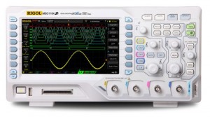
Rigol’s MSO1104Z combined 100MHz of Analog Performance on 4 channels along with 16 Digital Channels for $1000 (MSRP: $997) USD! That’s an amazing package. Full specs and Quote request available here.
MinutePhysics, one of my favorite YouTube channels, has done a collaboration project to provide an animated short on a scientifically correct version of the Children’s song, “Twinkle Twinkle Little Star.”
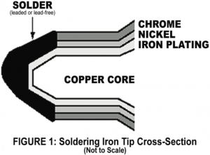
After mentioning how much I like using a brass sponge when soldering, I came across this App Note from OK International. This is a great note to read through. It discusses what is inside of a soldering iron tip, why they fail, and how to keep them in good shape.
Image from OK International’s Tech Note
The note actually makes me realize two of my own mistakes.
First, most cleaning should be done with a wet sponge not the brass sponge. (Oops!)
Second, pre-made tip tinners are meant for occasional cleaning. Moving forward I think I’ll modify my soldering behavior so that I start with a quick clean in the brass, use the sponge while working on a board, and then use standard solder to protect the tip when done.
What other tips (no pun intended) can you think of for soldering tips?
Like other websites, this one uses cookies to remember things. Mostly, I use Google Analytics to know how many people come here. ¯\_(ツ)_/¯
By clicking “Accept”, you consent to the use of ALL the cookies.
This website uses cookies to improve your experience while you navigate through the website. Out of these, the cookies that are categorized as necessary are stored on your browser as they are essential for the working of basic functionalities of the website. We also use third-party cookies that help us analyze and understand how you use this website. These cookies will be stored in your browser only with your consent. You also have the option to opt-out of these cookies. But opting out of some of these cookies may affect your browsing experience.
Necessary cookies are absolutely essential for the website to function properly. These cookies ensure basic functionalities and security features of the website, anonymously.
Cookie
Duration
Description
cookielawinfo-checkbox-advertisement
1 year
Set by the GDPR Cookie Consent plugin, this cookie is used to record the user consent for the cookies in the "Advertisement" category .
cookielawinfo-checkbox-analytics
11 months
This cookie is set by GDPR Cookie Consent plugin. The cookie is used to store the user consent for the cookies in the category "Analytics".
cookielawinfo-checkbox-functional
11 months
The cookie is set by GDPR cookie consent to record the user consent for the cookies in the category "Functional".
cookielawinfo-checkbox-necessary
11 months
This cookie is set by GDPR Cookie Consent plugin. The cookies is used to store the user consent for the cookies in the category "Necessary".
cookielawinfo-checkbox-others
11 months
This cookie is set by GDPR Cookie Consent plugin. The cookie is used to store the user consent for the cookies in the category "Other.
cookielawinfo-checkbox-performance
11 months
This cookie is set by GDPR Cookie Consent plugin. The cookie is used to store the user consent for the cookies in the category "Performance".
CookieLawInfoConsent
1 year
Records the default button state of the corresponding category & the status of CCPA. It works only in coordination with the primary cookie.
viewed_cookie_policy
11 months
The cookie is set by the GDPR Cookie Consent plugin and is used to store whether or not user has consented to the use of cookies. It does not store any personal data.
Functional cookies help to perform certain functionalities like sharing the content of the website on social media platforms, collect feedbacks, and other third-party features.
Cookie
Duration
Description
language
session
This cookie is used to store the language preference of the user.
Performance cookies are used to understand and analyze the key performance indexes of the website which helps in delivering a better user experience for the visitors.
Analytical cookies are used to understand how visitors interact with the website. These cookies help provide information on metrics the number of visitors, bounce rate, traffic source, etc.
Cookie
Duration
Description
_ga
2 years
The _ga cookie, installed by Google Analytics, calculates visitor, session and campaign data and also keeps track of site usage for the site's analytics report. The cookie stores information anonymously and assigns a randomly generated number to recognize unique visitors.
_ga_LHR6J24XSY
2 years
This cookie is installed by Google Analytics.
_gat_gtag_UA_42726312_1
1 minute
Set by Google to distinguish users.
_gid
1 day
Installed by Google Analytics, _gid cookie stores information on how visitors use a website, while also creating an analytics report of the website's performance. Some of the data that are collected include the number of visitors, their source, and the pages they visit anonymously.
browser_id
5 years
This cookie is used for identifying the visitor browser on re-visit to the website.
CONSENT
2 years
YouTube sets this cookie via embedded youtube-videos and registers anonymous statistical data.
Advertisement cookies are used to provide visitors with relevant ads and marketing campaigns. These cookies track visitors across websites and collect information to provide customized ads.
Cookie
Duration
Description
VISITOR_INFO1_LIVE
5 months 27 days
A cookie set by YouTube to measure bandwidth that determines whether the user gets the new or old player interface.
YSC
session
YSC cookie is set by Youtube and is used to track the views of embedded videos on Youtube pages.
yt-remote-connected-devices
never
YouTube sets this cookie to store the video preferences of the user using embedded YouTube video.
yt-remote-device-id
never
YouTube sets this cookie to store the video preferences of the user using embedded YouTube video.
yt.innertube::nextId
never
This cookie, set by YouTube, registers a unique ID to store data on what videos from YouTube the user has seen.
yt.innertube::requests
never
This cookie, set by YouTube, registers a unique ID to store data on what videos from YouTube the user has seen.