Author

James Lewis

Browsing

The first part of the tutorial looks inside of a Brushless DC Motor, or, BLDC. Then I show a discrete transistor circuit that can drive one. Of course, you’ll need a Microcontroller like an Arduino to drive it! Lastly, I briefly talk about an ESC.

Overall, a BLDC is better than a Brushed DC Motor (talked about those on #20) because:

  1. There are no brushes to wear out
  2. No sparks when the motor spins
  3. You can get way faster RPMs out of a BLDC.

Check out the AddOhms #21: Brushless DC (BLDC) Motors. Show notes are available here.

Previously, I reviewed the smartphone DMM, Mooshimeter. It is a great meter. One feature I didn’t spend much time on in my review was the ability to graph. Some see it as an “oscilloscope alternative.” The past couple of weeks, I’ve been using Aeroscope. It is a Bluetooth-based oscilloscope about the size of an older active probe. The Aeroscope runs $199 direct from Aeroscope Labs. The question I address in this Aeroscope review: is it better to buy this, a USB-based, or standalone scope for about the same money. How does it measure up?

My Aeroscope review looks at the specifications, the App that runs it and breaks down the key features. Let’s probe deeper.

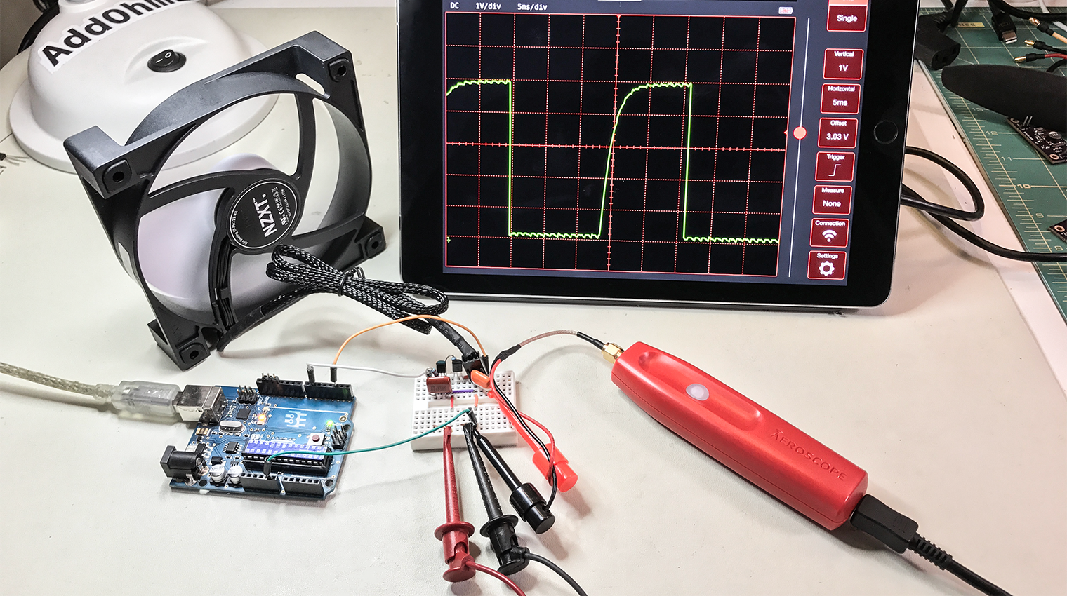
A question came up on IRC regarding how to PWM a 3-pin PC fan with an Arduino using analogWrite(). Controlling the fan was seemingly straightforward. The problem was that the hall effect sensor, or TACH signal, was incredibly noisy. The noise made it impossible to measure the fan’s rotation. Working through the question, I found three issues to tackle:

  1. You need to use a PNP transistor
  2. Filter capacitors help
  3. Create a non-blocking RPM measurement (with millis())

This post addresses all three issues regarding how to PWM a 3-pin PC fan with an Arduino.

During #22 of the Hardware Developers Didactic Galactic meetup, I discussed Oscilloscopes. (Previously James talked about capacitors.) In the presentation, I broke down the internals of an oscilloscope. The presentation started off with a block diagram. Then I discussed the main components: vertical amplifier, A/D, memory controller, some of the computer side stuff, and the keynote was on triggering.

The trigger circuit of an oscilloscope fascinated me since very early in my HP/Agilent career. When I saw trigger modes like Pulse, Violation, Rise Time, and “Runt,” I thought: Wow, this must be the most complicated circuit in the scope! While it isn’t trivial, it very clever how just a few pieces of (relatively) simple hardware drive one of the most important aspects of a digital scope.

Download Slides

Rick Altherr also gave an excellent talk on ECUs and their sensors. (I always thought ECU only meant engine control unit. His talk helped me understand why that isn’t really the case anymore!) It was great to learn about the combination of the engine mechanics with the electronics that control it. !)

See Rick’s Slides