What is the Pi Cap?
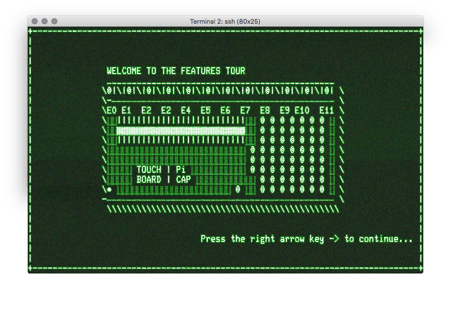
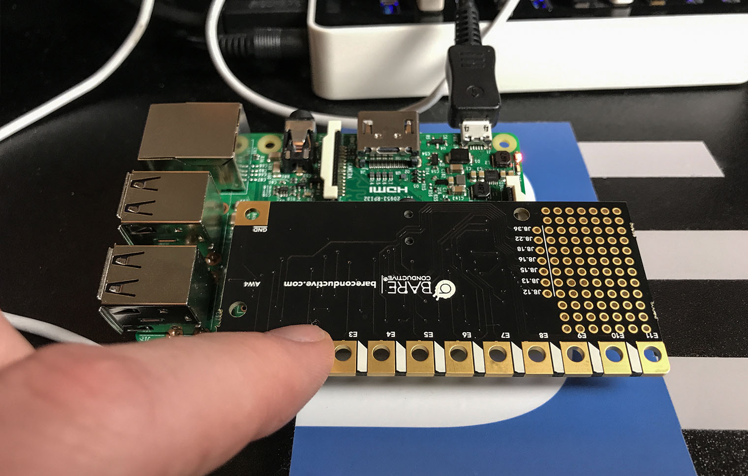
Arduino tends to call daughter cards shields, while the Raspberry Pi community calls them hats. The Pi Cap is a hat. It plugs into the GPIO header of a Raspberry Pi and provides 13 capacitive touch pads. There is a traditional push button, an LED, and a prototyping area. While the Pi Cap does consume all of the GPIO pins, several are broken out near the GPIO header.Pi Cap Form Factor
The hat will physically fit with any of the “regular” Pi and Zero form factors. The conductive pads extend slightly past the edge of the Pi. It seems the Pi was designed specifically for the Zero. When attached, the combo will sit flat on a table with the Pi Cap on the bottom. This configuration makes for easy presses and connecting to conductive ink pads. However, the Raspberry Pi modules with USB and Ethernet ports cause the board to sit a bit funny. I did like that there is a blue LED and it has been designed to be visible through a mounting hole. Pretty smart.Installing the software
For my testing, I started out with a new Jessie Lite install. My existing Pi is setup for the Raspberry Pi Soft Power Controller. The RPSPC requires at least 1 GPIO pin to keep the supply active, so I could not keep Pi booted with the Pi Cap taking up all of the GPIO pins. Installing the support files and examples for Pi Cap is simple:sudo apt-get install picapPin Mapping
At first, I expected the touch pads to map to a GPIO pins on the Pi. Then I realized, that does not really make sense. The touch controller is an NXP MRP121. At least, based on the library with the examples.Examples
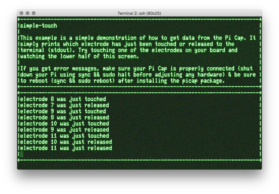
Speaking of the examples, they come in four different formats. Of course, there are Python examples. Also included are examples for Processing (the Arduino IDE-like UI for PCs), C++, and even node.js. In my Pi Cap hands on, I only used the C++ examples. (Note, they are stored in the CPP folder.) There is a script included that compiles the example code and then runs it. Nice touch if you are not familiar with the build process. These examples include a simple touch example which tells you when you press and let go of a conductive pad. As well as an MQTT example.
Issue with the button
As mentioned, there is a physical push button on the shield. In my testing, I ran into a snag. While running the “button utility” example, the Pi would completely lock up. I did not spend enough time to diagnose the problem. Either the code was causing a lock up or the physical moving of the shield when I pressed the button did. The physical push button, on a Raspberry Pi 3, is right next to a USB connector. It is challenging to reach the button. At least, without rocking the hat back and forth.Pi Cap Audio
There is an audio output available. However, I did not have anything to plug into it. I could see the port enabling a virtual piano. Or, adding sound effects as the capacitive buttons are pressed. More Info on Pi CapConclusion
Here’s where I am stuck. I think the Pi Cap is an interesting utility or tool. However, I cannot think of any applications I want to use it. It is not possible to attach an LCD to the Pi, so that means you are looking at a headless application. Or something with some LEDs. But, there are limits to the GPIO available. When pressing individual pads, I found it difficult to press only one pad. It seemed like I was always triggering two at a time. However, the limit of my creativity should not be your limit. I would like your help.
What can I use this hat to build? What projects can YOU suggest for such a device?


7 Comments
Not sure about your comment on connecting an LCD. How about using an I2C LCD module? Or some of those I2C LED matrix that people like Adafruit supply.
You’d have to build some custom hardware to access the I2C pins. Like an interposer board. The cap takes up the entire GPIO area and only 7 general purpose pins are broken out.
you can make a code lock, add a rgb led to signal fail or succes.
I thought about that one. But seems like a Pi would be overkill. What else could the Pi be doing?
Well, you could make it a really intelligent lock by adding checks for my actual presence (telephone or fitbit bracelet via bluetooth) or facerecognition using the camera. Add a schedule (no need to open the drinks cabinet unless on a weekend, no need to open the gun vault unless the shooting club is open that day).
the keypad can be in a central place in the house, no need to have one on each door/cupboard.
It would be possible to have several codes tied to different profiles. When my housekeeper logs in she would be able to get to the cupboard with the bleach but not the drinks cabinet, when my children come home from school they can unlock the fridge and have a coke but no bleach or whiskey for them.
Codes can be valid once so the ups guy or the meter man can enter the hallway (while pi sends me a mail about that and logs the stuff)
Multifactor authentication (BT device, face recon, etc with keypad) is an interesting idea.
I found the Audio output placed underneath the board as a bad idea. Otherwise it worked well.