Logic probes are great for debugging 7400 series logic chips and digital circuits. In this video, James makes a counter circuit and debugs each stage as he builds, with a Logic Probe. If you are wondering, “do I need a logic probe” this video shows how one can be used and even answers when you should consider buying one.
A spectrum analyzer displays signals in the frequency domain. To use one, you only need to know about four controls: reference level, center frequency, and resolution bandwidth. In this episode, see how to use a spectrum analyzer and determine the transmitting frequency of a device.
The example device is my microphone transmitter. It operates around 500 MHz with FM modulation. You’ll see how I step through the spectrum analyzer controls to find the exact frequency. At the end of the episode, I show some advanced measurements you can do with a modern spectrum analyzer. My favorite one is the demodulation.
There are three capacitor measurements you need to know how to make: capacitance, leakage current, and equivalent series resistance. Capacitance is easy to measure if you have a current limited supply or can use a resistor. Apply a voltage, then time how long it takes to charge up. You might need to use an oscilloscope or even an Arduino for the second part. Leakage current is the easiest of the three, apply a voltage (ideally through a resistor) for a few minutes, and then measure the current. ESR requires some special tricks. Since it is the resistance of the “wires” connecting to the capacitive element’s anode and code, you have to measure resistance without charging up the capacitor. (Otherwise, you get leakage.)
In the post Measuring Aluminum Electrolytic Capacitor’s ESR, I go through those methods in more detail. I also introduce the PEAK Electronics ESR70. It’s a pocket-sized instrument that measures both Capacitance and ESR. There’s a button you can touch, or it detects when a new capacitor is connected. Check out my Workbench Wednesdays review where I go into depth about how the meter works (and whether or not I like it.) Oh one bonus feature, it works while in-circuit!
As of this post, it has been almost six years since I first wrote about capacitors on my blog. The article was the Arduino GSM Shield’s capacitor has a serious design flaw. Wow, how time passes.
More info on element14The TENMA 72-2660 portable power supply offers bench supply capability in a backpack-friendly package. The single output is capable of 45 watts with up to 30 volts and 3.75 amps out. The built-in USB ports offer an easy way to power 5 Volts Arduino or Raspberry Pi projects while limiting their current. See how this portable supply performs, the things the Bald Engineer likes about it, and the points to consider before buying
This $100 power supply, model number 72-2660, is cool. It’s about the size of a digital multimeter but can output 45 Watts. Both voltage and current are adjustable. It can output up to 30 volts and 3.75 amps, but not at the same time. It does have a flaw in its design though. Fortunately, I was able to find and apply a fix for it. Overall, if you want a portable adjustable supply, this one is worth checking out.
If you are new to bench or lab power supplies, check out this bench power supply basics video.
To answer a common question: yes, I did injure my shoulder. Right before shooting the A-Roll, the parts with me on camera, I tripped. As I went to catch myself falling, I tore two of the muscles in my shoulder. It took about 6 weeks to completely heal. Yuck!
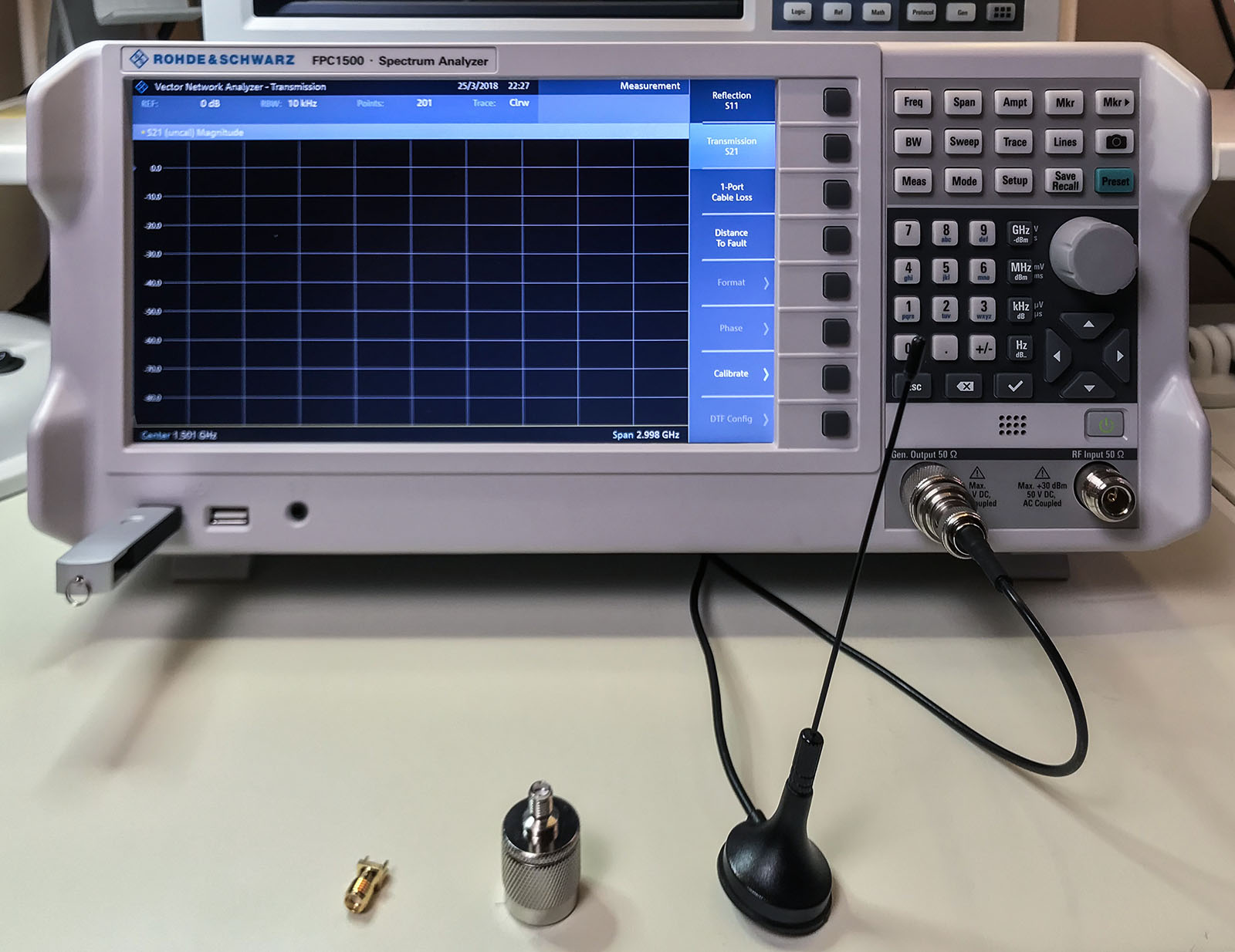
Show notes on element14Everyone’s first piece of test equipment should be a multimeter. Next is probably a power supply with current limiting. For many engineers, the next step is an oscilloscope. At least those working on digital electronics. Even if you are not working with RF, do not overlook a spectrum analyzer. The Rohde & Schwarz FPC1500 is three instruments in one: a Spectrum Analyzer, RF Signal Source, and a Vector Network Analyzer. In this post, I combine an FPC1500 review with an introduction to these frequency domain tools.
tl;dr; I recommend buying the FPC1500.


