Category

KiCad

Category

KiCad KiCon 2019 BannerOn April 26th and 27th, the first year of KiCad KiCon kicks off in the Windy City. Join me and 26 others for talks about the open source electronics CAD tool. The list of speakers is impressive. There are many names which I follow on social media and some I recognize from the KiCad team. For example, Wayne Stambaugh is the KiCad project leader and has one of the keynote talks.

You can see the full list of KiCon talks here. And tickets are available here.

Bald Engineer’s Apple IIgs KiCon Talk

Here is the description for my KiCon talk.

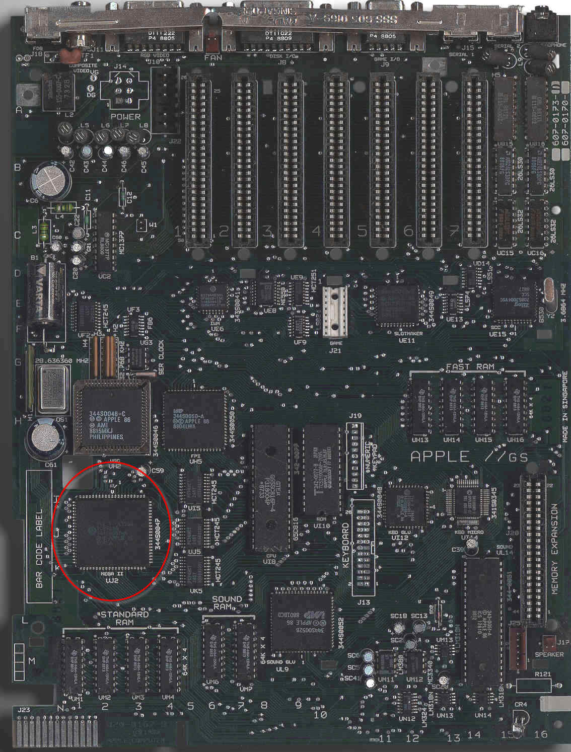
While documentation exists for 1970’s and 1980’s calculators and computers, unfortunately they exist in bitmap formats. As I started converting parts of the Apple IIgs schematic to KiCad, I realized something. There are benefits to “preserving” historical schematics in a living, active, and open format. In this talk, I talk about my experiences in converting scanned PDFs into KiCad, the project behind that motivation, and to encourage help from others to preserve history with KiCad.

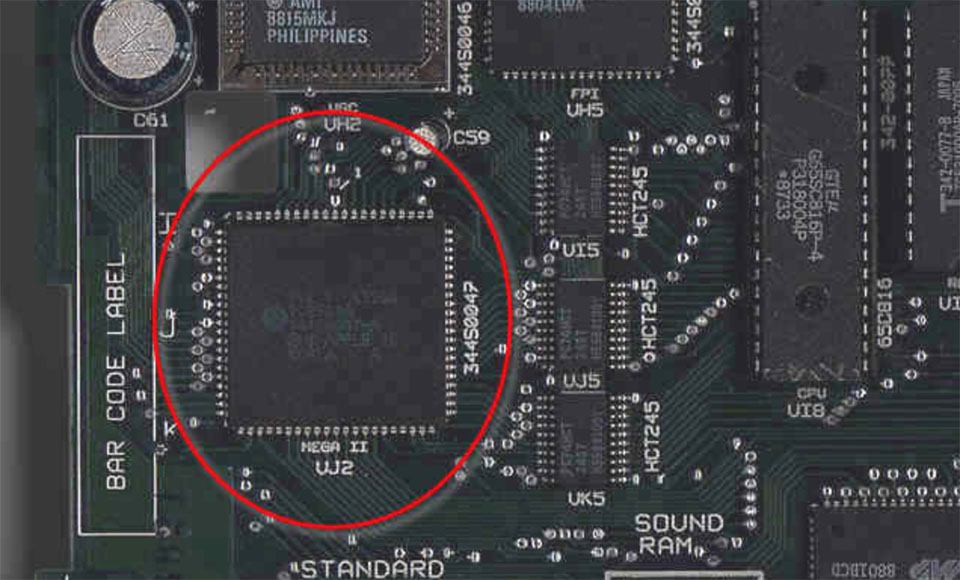
So what is it? Well, several months ago, I did a couple of Apple IIgs hardware live streams. I have a project in mind for the MEGA-II ASIC. But before I could move forward on the project, I wanted a modern version of the IIgs schematic.

While schematics for classic 8 (and 16-bit) computers are readily available, they are usually only in PDF format. Studying the design is like reading a book. While I am glad the PDFs are available, I would like to be able to do actions like a search.

In my talk, I’ll explain why we should be converting these classic schematics into an open format. Along the way, I’ll take the audience through my journey of using KiCad for this project. In the end, I’ll be asking for help to convert other classic computer schematics.

Where is KiCad KiCon 2019?

The location for the conference is mHUB in Chicago, IL. If you’re able to attend in person, I look forward to meeting you. If you’re not able to travel, I fully expect either a live stream or recorded versions of the talks to be available.

Learn more about KiCad KiCon 2019
2020-04-04: This tutorial is based on KiCad 5. With KiCad 6, the bus feature works a little different (so I’m told.)

When your schematic has a large number of related signals, it is helpful to group them. In its schematic editor, KiCad has a few tools to help. Your end-goal helps determine which tools to use. For example, do you need a KiCad bus or a label? In this post, I explore how you can define signals, group them, and reference them across schematic sheets.

Up until recently, I did not need to use a bus or multiple sheets. However, the Apple IIgs project I’m working on is too large for a single page. In a KiCad live stream, I looked at how to create busses and connect them. In a separate tutorial, I will show how to work with multiple sheets in KiCad.

tldr; KiCad does not require the use of a bus to connect signals together. Wire labels already provide that connection. A KiCad bus offers two things: 1) a visual representation and 2) an easier way to create global connections (across sheets.)

Lastly, if you are not familiar, KiCad is an Open Source eCAD tool. Although I have used others, this one currently my preferred platform.

KiCad Bus, Label, and Wire

Before jumping to how to use a bus, first, we need to start with the basics. KiCad connects nodes with a “wire” element. KiCad gives each wire drawn a unique name unless it connects to an existing node. The user can override the name by adding a label.

KiCad Wire and Label Example
Wire and Label Example

A new project I have started working on involves the Apple IIgs. It was Apple’s last 16-bit (and 8-bit) computer. Inside are many application specific integrated circuits, or ASICs, that make the IIgs an extraordinary member of the Apple II family. One chip, in particular, is called the “MEGA-II.” This chip takes all of the individual logic chips from the original Apple II design and incorporates them into a single 84-pin PLCC.

The project I have in mind needs the MEGA-II. I need to design some printed circuit boards for it and a few other IIgs chips. That goal means I need at least one custom Kicad schematic symbol. I plan to create a custom library of Apple IIgs components.

Like other computers from the same era, complete schematics are available. However, they are not in a modern format. Since I need to create symbols for so many of the chips as it is, I may end up re-creating the entire IIgs schematic.

For now, here is the process I use to create custom KiCad schematic symbols and parts.

There is a project that has been sitting on my “to do” list for too long. My lab notebook has several dedicated pages for it. But I have not made progress. I decided to take some advice I have given to other people. When you’re stuck on starting a task, break down the project until you find a piece small enough you can get it done with no problem.

The project involves the Apple IIgs. It was Apple’s last 16-bit (and 8-bit) computer. Inside are some application specific integrated circuits or ASICs that make the IIgs. The name with my attention is named “MEGA-II.” It takes all of the individual logic chips from the original Apple II design and incorporates them into a single 84-pin PLCC.

MegaII from AppleLogic 960px
Image from Applelogic.org (Full)

Continuing the DIY Arduino tutorial series, this AddOhms episode shows how to create a PCB in KiCad. I make a joke that the original design was a rectangle, which I found boring and pointless. So instead, I designed a triangle to give the board 3 points. Get it? Puns! I am calling it the Pryamiduino. To be honest, I found not having a constraint to be a problem. By forcing a specific board size and shape, many decisions were more manageable.

boring rectangular arduino nano clone
First design – Boring!

In the end, the video ended up more edited than I planned. KiCad is just so finicky and crashy that I could not make a coherent start to finish tutorial. At least, I could not work with a board at this level of complexity. Something simple like a 555 flasher would be easier to show from start to finish. I am planning some immediate follow-ups with quick tips on using KiCad. It is a frustrating suite of applications, but the results can be quite nice.

AddOhms Pyramiduino Show Notes