Category

Blog

Category

When connecting multiple oscilloscope probes to a circuit, does each probe need to connect to ground?

The short answer is yes!

Why? The long answer is kind because of the ground loop. Remember, a circuit needs a closed path. And while on DC circuits we may rarely think about the distance of that path, it absolutely matters when there is an AC or frequency component.

When you do not connect each probe’s ground, the signal path because enormous since it must connect to the circuit’s ground through another probe. (See the animation in the video above.)

Every digital oscilloscope I have ever used has a menu or dialog for “acquisition modes.” And depending on the current settings, changing that acquisition mode does not seem to have an effect on the signal. Or sometimes, changing to something like Average mode can completely destroy your measurements.

It turns out, that the analog-to-digital converters in digital oscilloscopes can do more than just “sample” the data. Well, the ADCs just samples. The controller behind the ADC offers modes like Peak Detect and Average and High-Resolution.

In general, the key to these modes is looking at a signal that is relatively slow compared to your sample rate. For example, on my R&S RTM3004, it samples up to 5 gigasamples per second. However, if you are only looking at a 10 MHz clock with a rise time in the 10s of nanoseconds, you don’t need to sample that fast.

Or, more correctly, you do not need to STORE data that fast. An acquisition mode, like Peak Detect, reduces (or decimates) the information stored. For example, it might look at 4 samples and ONLY store the max and min values of those four. That way, you get half the effective sample rate, but your peak-to-peak voltage measurement will still be correct!

This Workbench Wednesdays video looks at various acquisition modes and addresses when to use Peak Detect, Averaging, and High-Resolution acquisition modes.

Bench power supplies are an essential piece of test equipment gear. And like most test gear, they have a wide range of capabilities. For example, the B&K Precision 9140 is a triple output supply that can output up to 300 watts. But, the basic capability isn’t what interested me about the supply. Instead, it was advanced features like rear panel triggers, adjustable slew rate, and built-in sequencing.

The element14 Community arranged for a B&K Precision 9140 power supply to be sent to me for a hands-on overview of those features.

fix broken polygons in kicad

In KiCad 6, using the Polygon tool makes square boards easy. Just select the Edge.Cuts layer, then the polygon tool, and draw a square. However, if you want custom shapes, then you need to connect multiple line segments together.

If you are not careful, the segments will not connect and you might get one of two errors. The first comes when you run DRC.

Error: Board has malformed outline (not a closed shape)

or, if you try to render the board in 3D (ALT-F3).

Board outline is missing or malformed. Run DRC for a full analysis.

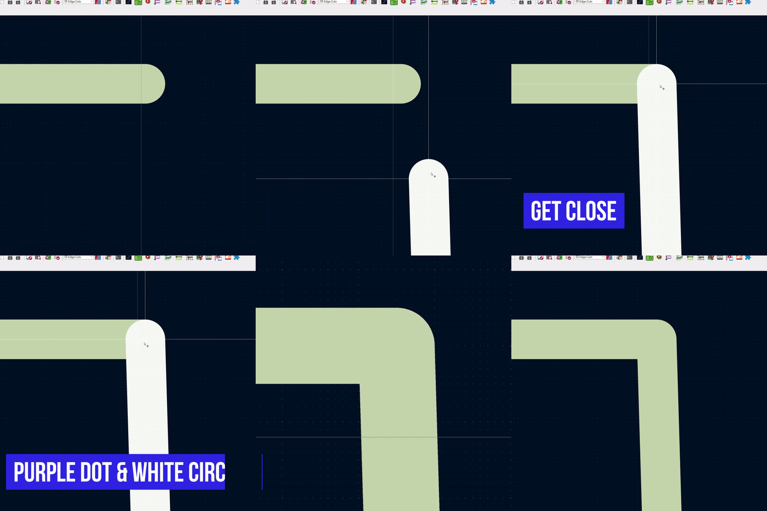
As the gif above shows, there is a small trick to connecting the segments. Zoom in, grab an endpoint, and then “snap” it to the other line. Watch carefully for a white circle to appear along with a purple box. Align those boxes and SNAP. Now the segments are connected together.

Thank you again to those who came over from RSS to say the old feed was working.

Also. My apologies for the rash of new posts. I *thought* I had a clever way to prevent them from appearing in the feed.

Let me know if you see any issues. New (real) posts will start in the next week or two.