Author

James Lewis

Browsing
2020-04-04: This tutorial is based on KiCad 5. With KiCad 6, the bus feature works a little different (so I’m told.)

When your schematic has a large number of related signals, it is helpful to group them. In its schematic editor, KiCad has a few tools to help. Your end-goal helps determine which tools to use. For example, do you need a KiCad bus or a label? In this post, I explore how you can define signals, group them, and reference them across schematic sheets.

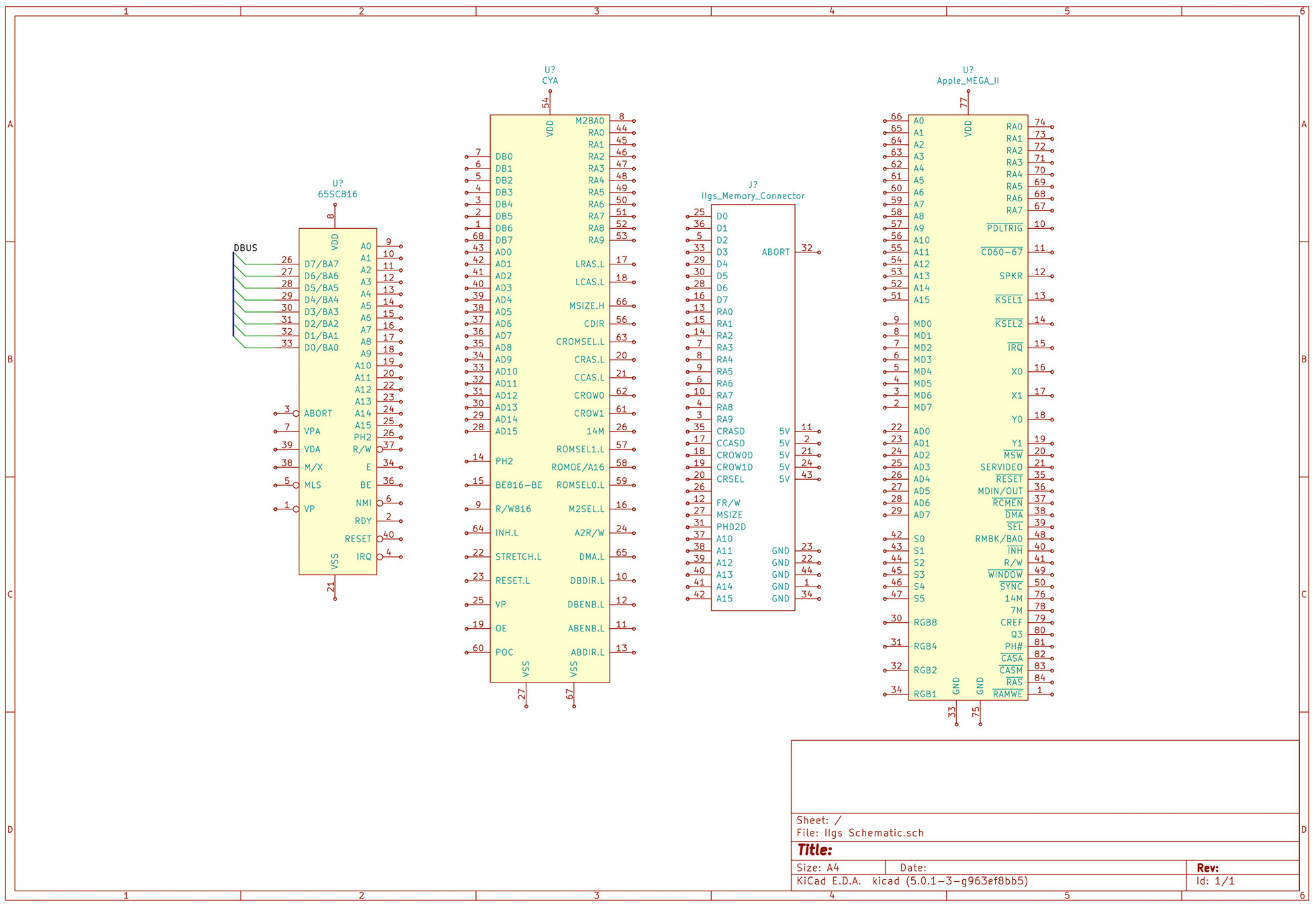
Up until recently, I did not need to use a bus or multiple sheets. However, the Apple IIgs project I’m working on is too large for a single page. In a KiCad live stream, I looked at how to create busses and connect them. In a separate tutorial, I will show how to work with multiple sheets in KiCad.

tldr; KiCad does not require the use of a bus to connect signals together. Wire labels already provide that connection. A KiCad bus offers two things: 1) a visual representation and 2) an easier way to create global connections (across sheets.)

Lastly, if you are not familiar, KiCad is an Open Source eCAD tool. Although I have used others, this one currently my preferred platform.

KiCad Bus, Label, and Wire

Before jumping to how to use a bus, first, we need to start with the basics. KiCad connects nodes with a “wire” element. KiCad gives each wire drawn a unique name unless it connects to an existing node. The user can override the name by adding a label.
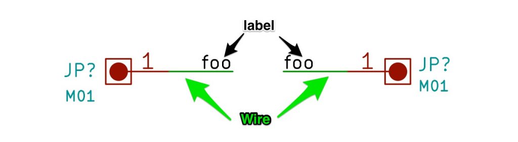
KiCad Wire and Label Example
Wire and Label Example

During a live stream, I was asked: “What is the Apple IIgs?” In this AddOhms Live Twitch Clip, I answer the question.

The Apple IIgs was the last of the highly successful Apple II line of computers. The “GS” stood for “graphics” and “sound.” Compared to previous Apple II computers, the IIgs was a fully 16-bit machine. When connected to its proprietary RGB monitor, it rendered a gorgeous display. Sadly, not much software took advantage of the improved graphics and sound capabilities. The IIgs was fully backward compatible with the older 8-bit line of Apple II computers. Its compatibility was so good that most IIgs users only used it in the compatibility mode.

How did the Apple IIgs achieve backward compatibility?

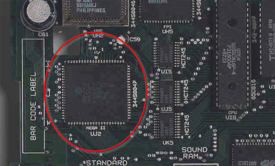
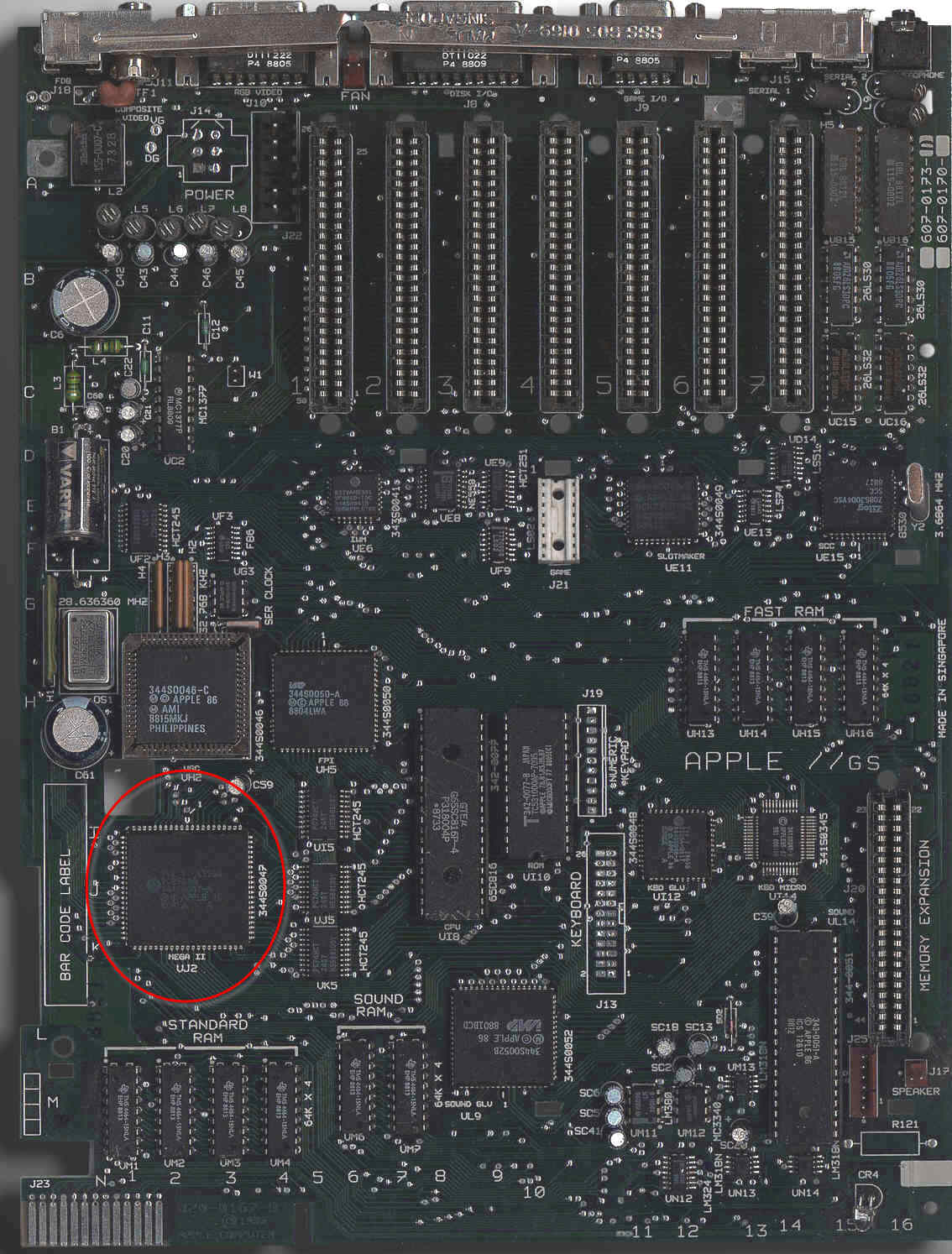
The IIgs contains an ASIC called the “MEGA-II.” (Which has nothing to do with the “Mega” Arduino boards.) It includes all of the individual logic chips from the original Apple II design as a single IC. Well, in addition to that IC you also need to add a CPU, RAM, and a ROM.

In my opinion, the Apple IIgs is best of the Apple IIs. In fact, of computers in that era, it is my overall favorite. When I got the IIgs, it replaced my previous pick: a Macintosh SE/30.

A new project I have started working on involves the Apple IIgs. It was Apple’s last 16-bit (and 8-bit) computer. Inside are many application specific integrated circuits, or ASICs, that make the IIgs an extraordinary member of the Apple II family. One chip, in particular, is called the “MEGA-II.” This chip takes all of the individual logic chips from the original Apple II design and incorporates them into a single 84-pin PLCC.

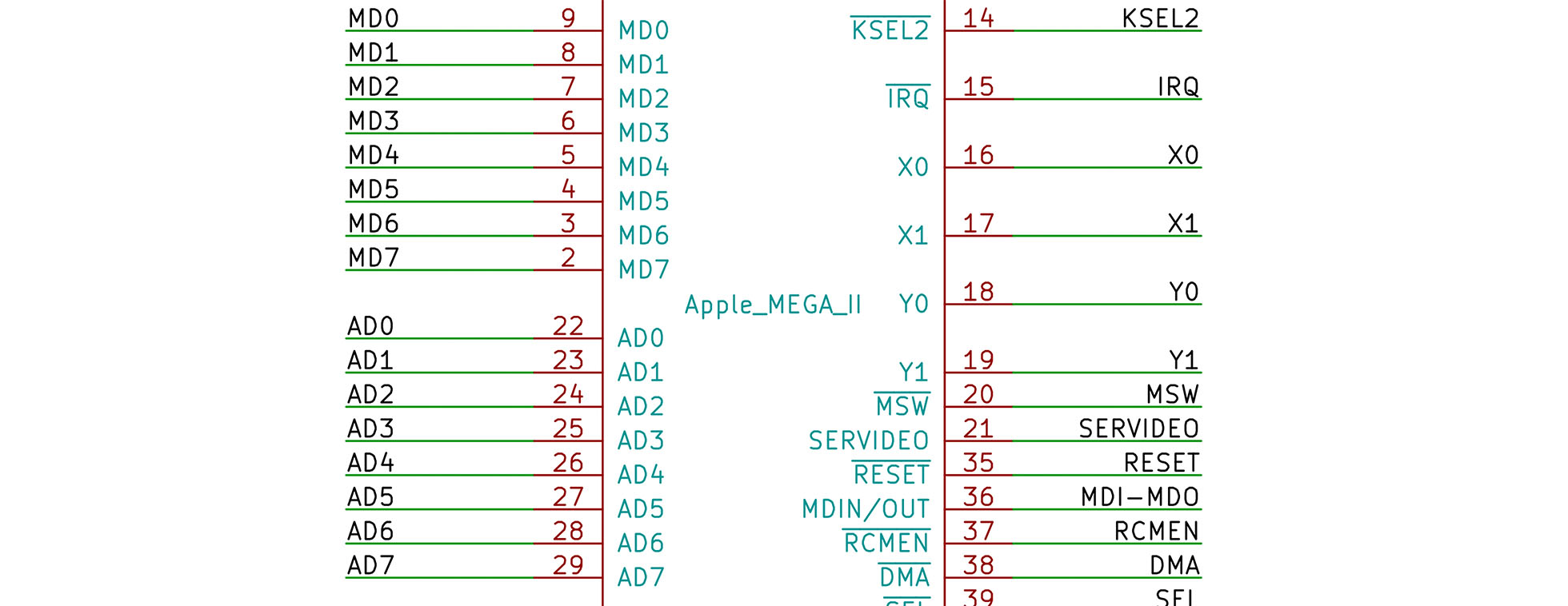
The project I have in mind needs the MEGA-II. I need to design some printed circuit boards for it and a few other IIgs chips. That goal means I need at least one custom Kicad schematic symbol. I plan to create a custom library of Apple IIgs components.

Like other computers from the same era, complete schematics are available. However, they are not in a modern format. Since I need to create symbols for so many of the chips as it is, I may end up re-creating the entire IIgs schematic.

For now, here is the process I use to create custom KiCad schematic symbols and parts.

There is a project that has been sitting on my “to do” list for too long. My lab notebook has several dedicated pages for it. But I have not made progress. I decided to take some advice I have given to other people. When you’re stuck on starting a task, break down the project until you find a piece small enough you can get it done with no problem.

The project involves the Apple IIgs. It was Apple’s last 16-bit (and 8-bit) computer. Inside are some application specific integrated circuits or ASICs that make the IIgs. The name with my attention is named “MEGA-II.” It takes all of the individual logic chips from the original Apple II design and incorporates them into a single 84-pin PLCC.

MegaII from AppleLogic 960px
Image from Applelogic.org (Full)

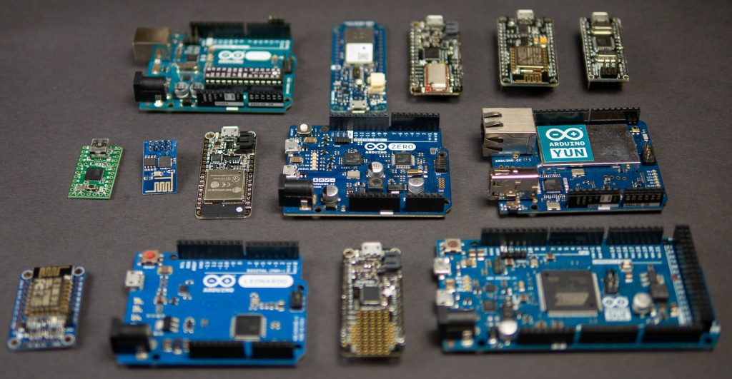
Looking through my parts boxes, I have counted at least 15 distinct “Arduino boards” in my collection. Either they are variants of the Uno form factor or they have different processors from the 8-bit boards. That number easily goes to 30 if I include boards with just the “Arduino header” on them. This pile of microcontrollers got me thinking, how does anyone ever choose the right board?

For example, I have had several people tell me the ESP32 is the “ultimate Arduino.” But is it? Well, yes and no. Extra hardware you do not need can lead to complexity and unexpected behavior. When using an advanced module like the ESP32, it is important to learn how to use sleep modes to limit current consumption, especially for battery applications. But if you need WiFi, Bluetooth, I2C, SPI, UART, and high-performance processing, capacitive touch, GPIO, and analog inputs then the ESP32 is an obvious choice.

As for the other boards, I have written a guide to picking the right Arduino. You can find it over on the Hackster.io blog.

Read: Picking an Arduino