An overlooked danger of electronics soldering is the fumes. While the smell and smoke may not be pleasant, the chemicals in the fumes can be harmful. Is solder made with lead(Pb) your only concern? Learn about where lead-free solder came from, what different flux types mean, and two ways to keep your air (and your lungs clean.)
In the video, I show a cheap “smoke eater” and a professional fume extractor. There is a cost difference of $50 and $700 between the two. However, either is better than having nothing.
The most popular AddOhms video is my short tutorial on MOSFET basics. In the years since I posted the video, people have sent me many questions. While answering those questions I’ve learned quite a bit as well. For example, in that video, I say that Vgs is the threshold to turn on the MOSFET. Well, it turns out, that is not entirely true. It is the threshold to turn it off! Oops. A minor point with a subtle difference, but a common MOSFET misconception.
In this post, I dispel that and other common myths and misconceptions around using MOSFETs. As with all engineering tips and tricks, this post is not a definitive guide to FETs. Instead, it is meant to be a guide to help you ask the right questions to design in the correct part.
1. Misconception: You don’t need resistors on the gate
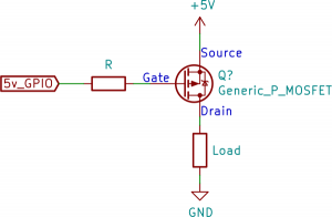
Back when I made the AddOhms episode, I added a resistor to the MOSFET’s gate pin. Of course any time a resistor is shown in a schematic, people get worried about what complicated formula is needed to determine its value. For slow switching applications, like below 10 kHz, the resistor value doesn’t matter. Something in the 100 to 1000 ohm range is fine.
P-Channel with series gate resistor
So if the value does not matter, why have one? The gate of a MOSFET is a small capacitor. And what happens when applying a voltage to a capacitor? It starts charging.
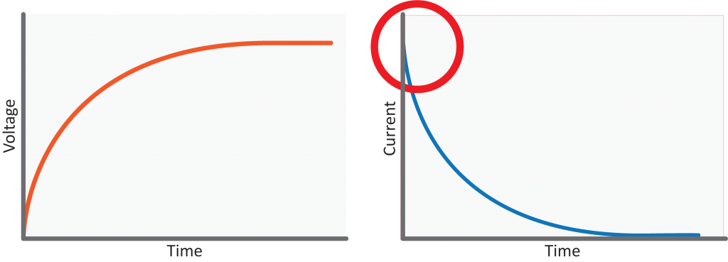
Resistor-Capacitor Charging Curve: Voltage and Current
The initial current is very high. It slows down as the capacitor charges. That initial current rush, also known as in-rush current, can be a problem. Even though it is a short time, there is a significant current surge that can damage an I/O pin. Depending on the size of the MOSFET’s gate capacitance, it may not be necessary to include that resistor. I wish I could say to “just” add it any time you use a MOSFET. If there is a high switching frequency, say 100 kHz or higher, then you have to worry about the RC charging curve created by the resistor and the gate capacitance.
Classic, vintage, or retro computer systems are well documented on sites like Wikipedia. Their historic position is well known. Their schematics are even published from original documentation. But how useful are those schematics in their current form? (Spoiler, not much.) Presented at KiCon 2019.
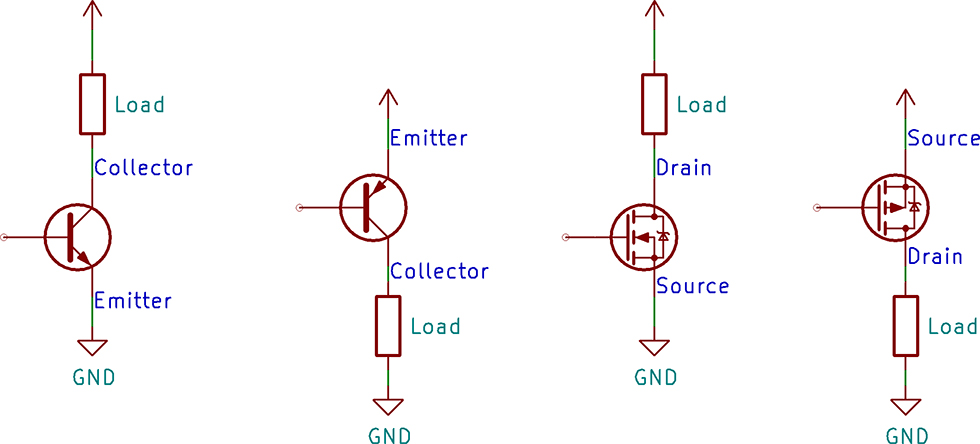
A common task for a transistor is switching a device on and off. There are two configurations for a transistor switch: low side and high side. The location of the transistor determines the type of circuit and its name. Either transistor configuration can use a BJT or MOSFET.
In this post, I draw the configuration for both transistor types, discuss which requires a driver, and explain why you would use either. If you are new to transistors, check out the resource links at the bottom. I have a few videos I made and some from element14’s The Learning Circuit, which do a great job introducing transistors.
On April 26th and 27th, the first year of KiCad KiCon kicks off in the Windy City. Join me and 26 others for talks about the open source electronics CAD tool. The list of speakers is impressive. There are many names which I follow on social media and some I recognize from the KiCad team. For example, Wayne Stambaugh is the KiCad project leader and has one of the keynote talks.
While documentation exists for 1970’s and 1980’s calculators and computers, unfortunately they exist in bitmap formats. As I started converting parts of the Apple IIgs schematic to KiCad, I realized something. There are benefits to “preserving” historical schematics in a living, active, and open format. In this talk, I talk about my experiences in converting scanned PDFs into KiCad, the project behind that motivation, and to encourage help from others to preserve history with KiCad.
So what is it? Well, several months ago, I did a couple of Apple IIgs hardware live streams. I have a project in mind for the MEGA-II ASIC. But before I could move forward on the project, I wanted a modern version of the IIgs schematic.
While schematics for classic 8 (and 16-bit) computers are readily available, they are usually only in PDF format. Studying the design is like reading a book. While I am glad the PDFs are available, I would like to be able to do actions like a search.
In my talk, I’ll explain why we should be converting these classic schematics into an open format. Along the way, I’ll take the audience through my journey of using KiCad for this project. In the end, I’ll be asking for help to convert other classic computer schematics.
Where is KiCad KiCon 2019?
The location for the conference is mHUB in Chicago, IL. If you’re able to attend in person, I look forward to meeting you. If you’re not able to travel, I fully expect either a live stream or recorded versions of the talks to be available.
Like other websites, this one uses cookies to remember things. Mostly, I use Google Analytics to know how many people come here. ¯\_(ツ)_/¯
By clicking “Accept”, you consent to the use of ALL the cookies.
This website uses cookies to improve your experience while you navigate through the website. Out of these, the cookies that are categorized as necessary are stored on your browser as they are essential for the working of basic functionalities of the website. We also use third-party cookies that help us analyze and understand how you use this website. These cookies will be stored in your browser only with your consent. You also have the option to opt-out of these cookies. But opting out of some of these cookies may affect your browsing experience.
Necessary cookies are absolutely essential for the website to function properly. These cookies ensure basic functionalities and security features of the website, anonymously.
Cookie
Duration
Description
cookielawinfo-checkbox-advertisement
1 year
Set by the GDPR Cookie Consent plugin, this cookie is used to record the user consent for the cookies in the "Advertisement" category .
cookielawinfo-checkbox-analytics
11 months
This cookie is set by GDPR Cookie Consent plugin. The cookie is used to store the user consent for the cookies in the category "Analytics".
cookielawinfo-checkbox-functional
11 months
The cookie is set by GDPR cookie consent to record the user consent for the cookies in the category "Functional".
cookielawinfo-checkbox-necessary
11 months
This cookie is set by GDPR Cookie Consent plugin. The cookies is used to store the user consent for the cookies in the category "Necessary".
cookielawinfo-checkbox-others
11 months
This cookie is set by GDPR Cookie Consent plugin. The cookie is used to store the user consent for the cookies in the category "Other.
cookielawinfo-checkbox-performance
11 months
This cookie is set by GDPR Cookie Consent plugin. The cookie is used to store the user consent for the cookies in the category "Performance".
CookieLawInfoConsent
1 year
Records the default button state of the corresponding category & the status of CCPA. It works only in coordination with the primary cookie.
viewed_cookie_policy
11 months
The cookie is set by the GDPR Cookie Consent plugin and is used to store whether or not user has consented to the use of cookies. It does not store any personal data.
Functional cookies help to perform certain functionalities like sharing the content of the website on social media platforms, collect feedbacks, and other third-party features.
Cookie
Duration
Description
language
session
This cookie is used to store the language preference of the user.
Performance cookies are used to understand and analyze the key performance indexes of the website which helps in delivering a better user experience for the visitors.
Analytical cookies are used to understand how visitors interact with the website. These cookies help provide information on metrics the number of visitors, bounce rate, traffic source, etc.
Cookie
Duration
Description
_ga
2 years
The _ga cookie, installed by Google Analytics, calculates visitor, session and campaign data and also keeps track of site usage for the site's analytics report. The cookie stores information anonymously and assigns a randomly generated number to recognize unique visitors.
_ga_LHR6J24XSY
2 years
This cookie is installed by Google Analytics.
_gat_gtag_UA_42726312_1
1 minute
Set by Google to distinguish users.
_gid
1 day
Installed by Google Analytics, _gid cookie stores information on how visitors use a website, while also creating an analytics report of the website's performance. Some of the data that are collected include the number of visitors, their source, and the pages they visit anonymously.
browser_id
5 years
This cookie is used for identifying the visitor browser on re-visit to the website.
CONSENT
2 years
YouTube sets this cookie via embedded youtube-videos and registers anonymous statistical data.
Advertisement cookies are used to provide visitors with relevant ads and marketing campaigns. These cookies track visitors across websites and collect information to provide customized ads.
Cookie
Duration
Description
VISITOR_INFO1_LIVE
5 months 27 days
A cookie set by YouTube to measure bandwidth that determines whether the user gets the new or old player interface.
YSC
session
YSC cookie is set by Youtube and is used to track the views of embedded videos on Youtube pages.
yt-remote-connected-devices
never
YouTube sets this cookie to store the video preferences of the user using embedded YouTube video.
yt-remote-device-id
never
YouTube sets this cookie to store the video preferences of the user using embedded YouTube video.
yt.innertube::nextId
never
This cookie, set by YouTube, registers a unique ID to store data on what videos from YouTube the user has seen.
yt.innertube::requests
never
This cookie, set by YouTube, registers a unique ID to store data on what videos from YouTube the user has seen.