
The Zener diode is often used to create a reference voltage. In tutorials and even college texts, there are mentions of creating a Zener diode based regulator. The idea is that the Zener maintains a known voltage drop. The problem is that current matters. This post looks a quick Zener diode overview and shows what happened when I tried to power a microcontroller using a “Zener diode regulator.”
Zener diodes overview
Just a brief overview if you are not familiar with Zener diodes. Like typical diodes, Zeners have low forward voltages. Typically you voltages are around 0.7. However, different material sets can offer different forward voltages.
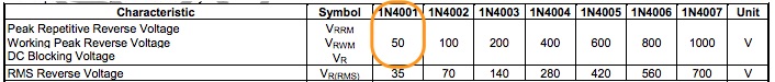
Also like generic diodes, there is a reverse breakdown voltage. If you look at a hefty diode like the 1n4001, you find breakdown voltages starting at 50 volts.
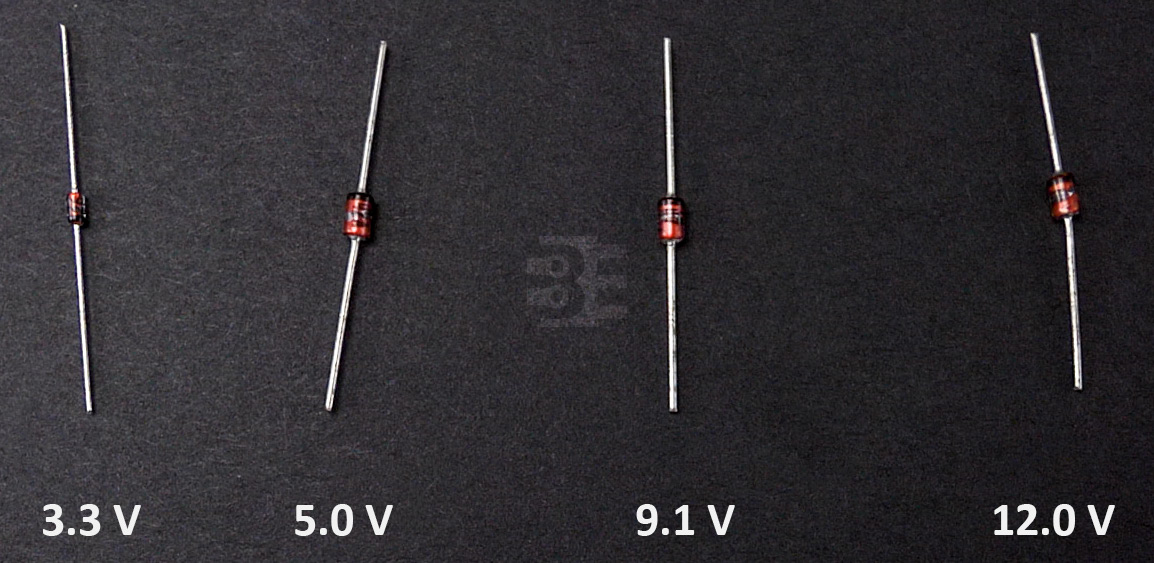
Zener diodes are unique because their reverse breakdown voltages are relatively low. For example, I have some that are 3.3, 5.0, 9.1, and 12 volts. (Interesting numbers, aren’t they?)
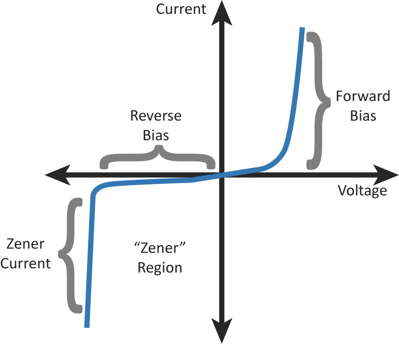
The curve is showing that above the forward voltage and “below” the reverse voltage, the diode conducts. I put below in quotes because it suggests a negative potential. This comment does not mean you need a negative voltage supply, just that the diode is reverse biased. Also known as turned around.
Zener diode regulator
As mentioned, the idea behind a Zener regulator is that the diode drops a stable voltage when reverse biased. Moreover, with values like the 3.3 and 5.0 I mentioned before, it starts to sound like a good option, doesn’t it?
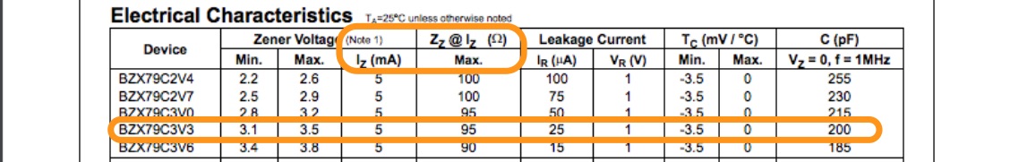
Let’s use the BZX79C3V3 as an example Zener diode. Notice in the characteristics table, that the reverse voltage is 3.3 volts at 5.0 milliamps.
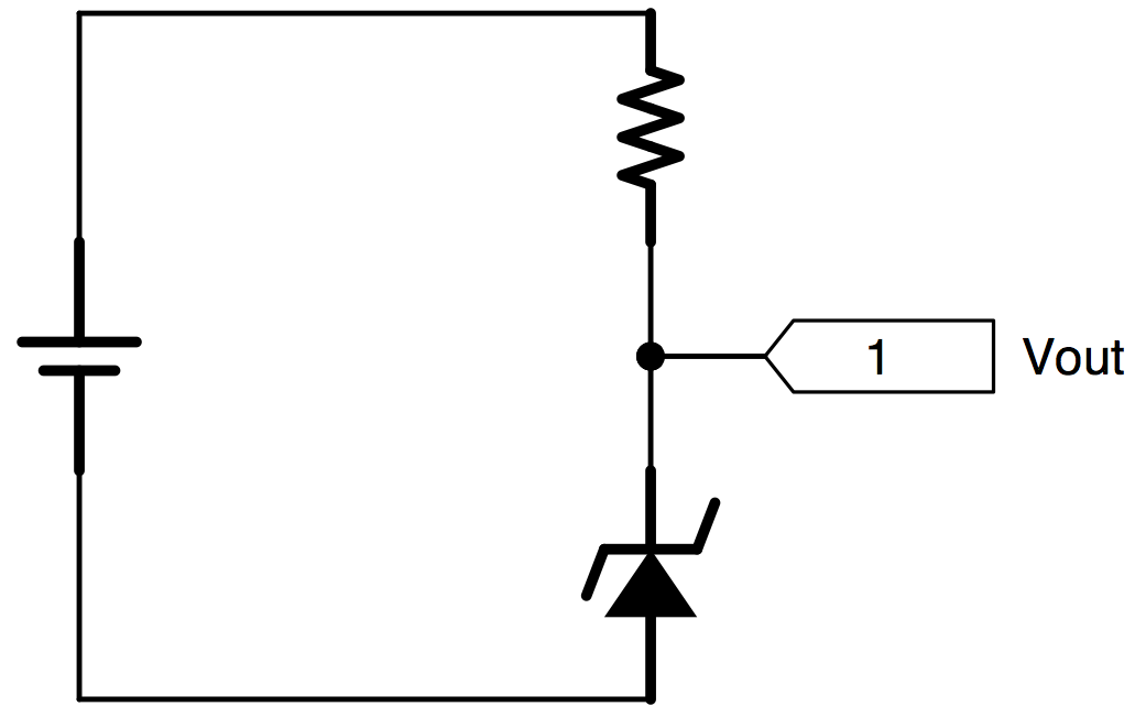
The idea is that you pick a resistor value, perhaps even a precision value, to create enough current to reverse bias the Zener diode at 5.0 milliamps.
However, there’s a problem with this basic circuit. The current that flows through the load must also flow through the resistor. Based on Ohm’s law, the resistor’s voltage drop changes based on its current flow.
Powering ESP8266 with Zener Regulator
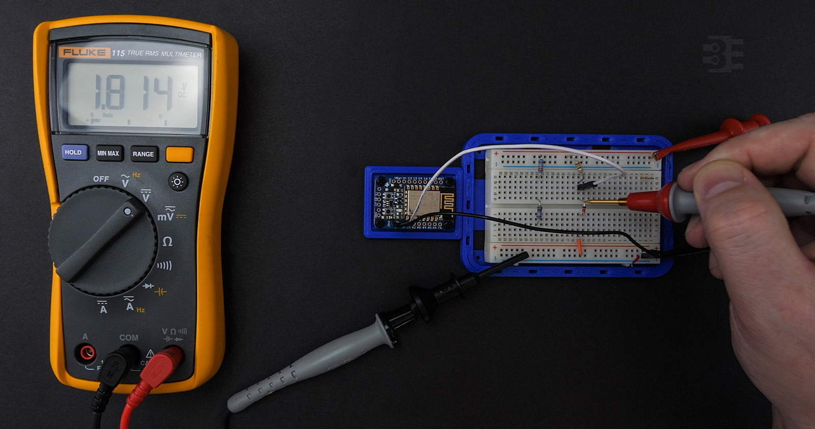
Using the above circuit, I tried to power an ESP8266 with a 5.0 volt supply. Before building this circuit, I measured the ESP8266’s current draw to be 60 milliamps when powered by a 3.3 volt supply.
Using a 3.3 volt Zener, the series resistor drops 1.7 volts. With 60 milliamps at the load and 5 milliamps for the Zener, Ohm’s Law tells us we need a 28Ω resistor. The closest value I have is 22 ohms.
\(\Huge R = \frac{E}{I} = \frac{1.7V}{60\mathrm{e}{-3}mA} = 28\Omega\)When I hooked the circuit up, nothing happened on the ESP8266. The VOUT node measured around 0.9 volts. What’s worse is that no matter what I made the source voltage, the VOUT node stayed at 0.9 volts.
On a hunch, I dropped resistor value by about 10 ohms.
When I measured with the multimeter, I saw only 1.8 volts at the divider. However, the ESP8266 was operating. After resetting the ESP8266, I saw 2.5 volts. And depending on how much weight was on my left or right foot, any value in between.
So what the heck is happening here? Well, first, thank you for continuing to read before jumping to the comments to say the following statement. You cannot treat a microcontroller, especially a system-on-chip (SOC), as a constant load.
When I press and hold the RESET button, the Vout node jumps to a nice clean 3.4 volts. At that point, most of the active circuits in the chip are turned off.
Since the ESP8266 was a high impedance load, nearly all of the current in this circuit is flowing throw the series resistor and the ESP8266. The amount of current was staggering, almost 200 mA. Well staggering when you might have only expected about sixty.
More Zener Regulator Problems
This entire exercise was to show why the Zener diode is a lousy regulator. The voltage drop depends too much on the current flowing through the junction. Which means the “regulator circuit,” depends on a constant load. Any active device is going to cause the VOUT node to be unstable.
So what good is this Zener regulator circuit? Well, it is not a regulator. Instead, it is a reference.
For example, you could use a similar circuit on Arduino’s AREF. Let’s say you are using an analog sensor that only outputs 3 volts maximum. Using a Zener reference could give the A/D more resolution.
You could use the Zener circuit as a reference into an op-amp. This circuit is not too different from how linear regulators work.
The lesson here is that if you want to use a Zener diode regulator circuit, you need to reconsider your design. In some very rare or corner cases, it will work fine.
If you have used a Zener as a regulator, and not as a reference, leave a comment below. I would love to hear how you used it.


29 Comments
I guess it all depends on what kind of “regulation” you need. If you need within 1% over a moderately varying range of loads and input voltages, then no. A zener+resistor is utterly inadequate. But in cases where the circuit is only going to draw, say, 2 to 10 mA, and you don’t need precision better than 1/2 a volt, a zener with a resistor that will draw 10x the required circuit current works just fine. i.e. a 12v zener + 100 ohm resistor with input voltage varying from 16 to 24v, for example. Sometimes, it’s handy to be able to just drop two little components on a board when you just need “close enough” voltage. Of course, the regulator is now wasting 90% of the circuit’s consumed power. But nobody ever promised it was efficient. Come to think of it, any linear regulator like an LM7812, is horribly inefficient (although much better at regulation).
I successfully used a 4.7V zener in series with an R220 resistor to cut a 9-12V p-p square wave down to near-TTL level, by placing the regulator on the square wave output. Since most or all clock inputs on TTL or CMOS chips are high impedance, this worked fine.
Hi, can put zener on the base of a high gain transistor. Less current variation and also circuit can supply more current, through transistor
I’ve a network of sensors on a common 5.5v maxim integrated 1-wire bus,, that have different tolerances. In this example, I’ve several chips with a max voltage of 3.9v. In order to power them, I’ve used a 13ma constant current source pullup on the 5.5v line (vs a simple pullup resistor), and at the sensors, used a simple diode and current limiting resistor to a 22uf cap. The 22uf cap is now the power source for vdd on all the sensors, and the 3.3v side of a transistor that is being used as a bi directional level shifter. The zenor diode is used as a regulator to drop the voltage to 3.9v which is the upper safe limit of the ic’s I’m using. If you ignore the fact I’m switching the 1-wire on and off,,, the upper 3.9v regulation is maintained even though the ic’s use different amounts of current depending on what is happening. The point is,, if using a current source instead of a voltage source, you are able to have much more variable load and still use a zener to regulate.
The constant current source is therefore acting as a variable series resistance, and I can see the usefulness for ensuring that the zener doesn’t overheat at minimum load current, but it seems you also have to have a tight control on maximum load current to ensure that the zener stays in the “constant” voltage part of its operating curve. Low voltage zeners tend to be really sloppy with regards to regulation at low zener current, so in these cases the load current may affect regulation much more than anticipated. I’d really like to see the complete schematic to get a better sense of what you’re doing, as I’m always looking for new ways to do things.
Curious if this or another diode would be perfect for my project. I have very limited space and need to step down a dc voltage of 6 to 5, with both the source and load consisting of power cells. Load needs to be as close to 5 as possible but no greater. If I can smack a diode in series and call it a day I will be a happy guy.
It depends on what that means. If the absolute upper limit is 5.00 volts, then maybe. It then depends on what lower voltage limit you can tolerate. But.
I would say, no, a diode won’t work. You need a low-drop out (LDO) voltage regulator.
So I am very curious why a zener diode a regular npn transistor and a mosfet transistor could not be used as a switching regulator. The circuit could be arranged in such a way that the diode would allow voltage in excess of it’s nominal vz into the gate of the npn transistor. The collector of the npn could be wired to the gate of the mosfet, and the emitter of the npn could be wired to the ground. The collector on the npn would be wired to unregulated voltage in, and the emitter of the npn would be the regulated side. The other end of the zener would be wired to the regulated side. When the regulated voltage in the circuit exceeds zener nom vz, it would pass to the emitter of the npn. The npn would bleed voltage off of the mosfet thus switching off the power from the unregulated side to the regulated side. What is wrong with this idea?
I meant the collector on the mosfet could be wired to to unregulated voltage in, and the emitter of the mosfet wired to regulated current.
Hi Stephen, I think you need to review your description carefully and clarify it if you want any sensible feedback. Like, is your MOSFET N- or P-channel? MOSFETs don’t have a collector, they have a source, drain and gate. Your “npn” does not seem to have a base connection. Are there any resistors?
If you mean to use ONLY a Zener and Transistor, then no this idea would not work. If it would, that is how switching regulators would be made today. They’re not.
Thank God for Google, as if found my exact phrase, which was also the title of your post here. 🙂 This is all the fault of teachers in Tech High schools, who draw the curve of a zener on a blackboard, and even point to text books, where the curve looks like a magical straight line. But as you observe, its totally dependent on current. Well guess what… if you have to supply a constant current to get a stabil reference, .I could argue that a resistor makes a good reference too! In fact in a lot of analog IC internal diagrams, where a Zener is part of the circuit, you see that familiar arrow in a circle, indicating a constant current feeding it. I have to say, I too have been dissapointed time and again using Zeners for anything. Except maybe tone shaping in guitar distortion pedals. 🙂
I’ve never seen just a resistor + a zener with nothing else touted as a complete voltage regulator; that’s wildly unstable. I see lots of old designs that buffer it with a transistor which gives it higher current output but doesn’t directly hold it steady. An op-amp buffer will hold it SPOT ON no matter what since it has an extremely high and constant input impedance. The only rub with that it that the output might choke if high current is needed and you aren’t using a high current op-amp. But add the transistor buffer after that and you’re golden: http://www.electronics-tutorial.net/wp-content/uploads/2015/09/VR12-300×147.png
Nice article, and pretty much gives a good “bird’s eye” view of zeners. The article title is certainly attention-grabbing, and I also congratulate the reader who reads through the entire article before posting a rebuttal in the comments section.
Back in the ’70s, these devices were very popular, especially with high-impedance loads and where changes in load impedance were relatively small. In those designs, the zener typically didn’t have to shunt a lot of current away from the load, and it was usually not too difficult to find a good range of resistances from which to choose. This was quite fortunate because resistor tolerances better than 10% weren’t as common as they are today, and the ubiquitous bulk carbon resistors of the day had gawd-awful drift.
Nowadays it’s not unusual for loads to swing from just a few milliamps (or microamps) to several hundred milliamps or more, and this calls for a lot more than just a “dumb” zener and series resistor. You found this out the hard way, but at least you learned from it. Goodness knows we all make our share of mistakes, but it’s the ones we repeat that are the worst!
James, you have my greatest resepct and I think you are doing a valuable service to the community. Please forgive me if my comments are too direct.
I think your conclusion, that a Zener diode makes a lousy regulator, is not correct. A Zener regulator, like any regulator, has to operate within some defined parameters. According to my understanding of your story, you did the wrong arithmetic at the outset, built a regulator that was operating outside its range, and as a result it did not work.
When used as a reference, the Zener diode is still a regulator, just for a rather low current, which makes the stress on the components low.
When a resistor-Zener chain is used as a regulator, the maximum and minimum current draw from the load needs to be taken into account. In the case of an ESP8266 as a load, its data sheet says it can range from about 170 mA down to almost zero. So if supplying 5.0 V and delivering 3.3V to the load, with a max load current of 170 mA, the resistor needs to be (5-3.3)/0.17 = 10 Ohms. The circuit will always draw 170ma from the supply. Sometimes it will flow through the load, sometimes through the Zener diode. It will always flow through the resistor. The resistor needs to be rated for at least 0.3 Watts (0.17A * 1.7 Volts) and the Zener diode needs to be rated for at least 0.6 Watts (3.3V * 0.17A).
I would say this is a rather wastefull, inefficient regulator. It gets worse if you take into account possible variability of the supply, and maybe other devices in parallel with the ESP8266.
Can I suggest a more useful question to address would be: what is the best/cheapest/simplest way of supplying 3.3V to ESP8266 plus a few peripherals, from a USB 5V supply? There might be 3 different answers to this. And maybe one of them IS the Zener regulator!
Excellent points. Thank you Keith.
The zener may be good as regulator if the load is less than the zener’s maximum current. But yes, it is kind of lousy. As reference, and constant current, is a WHOLE LOT better. I built a dual voltage bench PSU some 25 years ago using 741’s and it always has lacked the extra 741 based constant current source I took for some following projects from the Op Amp Cookbook. The simple resistor fed zener reference voltage changes with temperature and time, which is driftier than I would like for some particular applications. At first I blamed a lousy pot, and did nothing. One day I substituted it for a multiturn pot, and did not remove the problem. Scooped over the zener with my DVM, patience and a cup of coffee, and … the voltage over the zener soars as it heats up after turn on, and then remains RATHER stable… some time I will have to build a better reference for that old and useful 0 to 25 V dual polarity bench supply.
All this is quite true of zeners… and that is why some beefy zeners in D04 cases exist. Its basically a shunt to GND when working so about as wasteful of ‘extra’ electrons as you can get. Zeners were quite popular in the 1970’s when the 3 Pin regulators were not as common… (or inexpensive). Since that time… zeners get more properly used as a better voltage reference to a constant load, like the input of an op amp or base of a transistor.
The rule of thumb with zener diodes, to have a reliable regulated voltage, is that the current on the resistor should be twice as much as the maximum current on the load. So, lots of electrons just heating the diode. In your study case, 200mA load would account for another 200mA on the zener, 0.66W (3.3V * 0.2A)
An alternate rule of thumb might be to:
[1] Specify your maximum input voltage requirements.
[2] Specify your minimum input voltage requirements.
[3] Specify your maximum load current requirements.
[4] Specify your minimum load current requirements. This might be nearly micro amps for a device that will go to sleep. This might mean, that the minimum load current is < Izt for this circuit to operate reliably.**
P_dissipated_zener = (I_resistor * Vzener)
[9] Choose a zener diode that will meet your Izt and power dissipation requirements.
Looks like my post got chopped up.
I don’t think WP liked your formatting, sorry about that. Happens to me sometimes too.
Timely post. I am trying to solve a power supply problem for a project that has space and voltage restrictions. I want to use a compact 6v source (2 stacked CR2 batteries) to power a servo and an Atmega32u4 BLE module. The servo is an intermittent peak load. There is a USB power-in with a regulator that drops Vin to 3.3v, BUT the Atmega has a direct connection to USB and is restricted to 5.5v max. A zener seems like an easy (and compact) way to drop the 6v a wee bit to keep the arduino bits happy. I imagine some testing is in order. Wisdom and perspective welcome!
I don’t follow. The ATmega32u4’s absolute max is 6 volts on VCC. With two CR2s driving the micro, even with full charge, they won’t be a full 6 volts.
The data sheet I looked at listed a range of 2.7 – 5.5v. The CR2’s will take hours to drop to that voltage. If 6V is workable, everything gets happy!
http://www.atmel.com/Images/Atmel-7766-8-bit-AVR-ATmega16U4-32U4_Datasheet.pdf
Yes, the recommended operating range is up to 5.5 volts. However, the absolute max is 6.0 volts. It is specified in the “absolute max” table of the electrical characteristics section. That said, you shouldn’t operate there unless you have to. CR2032 batteries have very significant ESR. They aren’t designed for high load applications. I think you’re going to find fresh batteries powering a microcontroller like the 32u4 aren’t going to be delivering 6.0 volts. It’s going to be less and drop very quickly.
If you are really, really concerned then just put any diode in series with the supply. It’ll drop 0.7 volts from the max voltage. Or you can look for a silicon germanium diode which has something like a 0.3 forward voltage drop.
“If you are really, really concerned then just put any diode in series with the supply. It’ll drop 0.7 volts from the max voltage. Or you can look for a silicon germanium diode which has something like a 0.3 forward voltage drop.”
I wouldn’t depend on the diode for that.
Look at the VF curves on a diode datasheet. If you have a very small current load, say just a microcontroller the VF may be very far down the slope because IF will be tiny.
Seriously consider a voltage regulator that is intended for this purpose, they are tiny, accurate, and can have a low Iq so they don’t bleed out your batteries. That is the right answer.
I went with a a 1N914, and just to clarify, I’m using CR2 3V lithium camera batteries – MUCH larger than coin cells. Thanks!
Evad makes a good case for a voltage regulator [such as a low-droput (LDO) type] instead of just a series diode, and this is a definite improvement over the diode-only suggestion.
However, if you are really interested in getting the best life out of a couple of small batteries in series, I’d recommend a switch-mode voltage converter in either the SEPIC or flyback topology. You can even get a switchmode regulator in a three-pin package (like the Recom RE-78 series, intended to be drop-in replacements for the very popular 78XX regulators). The energy efficiency of a switch-mode converter is well-suited for battery operation, especially when space limitations require small batteries with limited energy content, and such a converter probably offers dramatically better battery life than even the most efficient linear regulator.