Tag

FPGA

Browsing

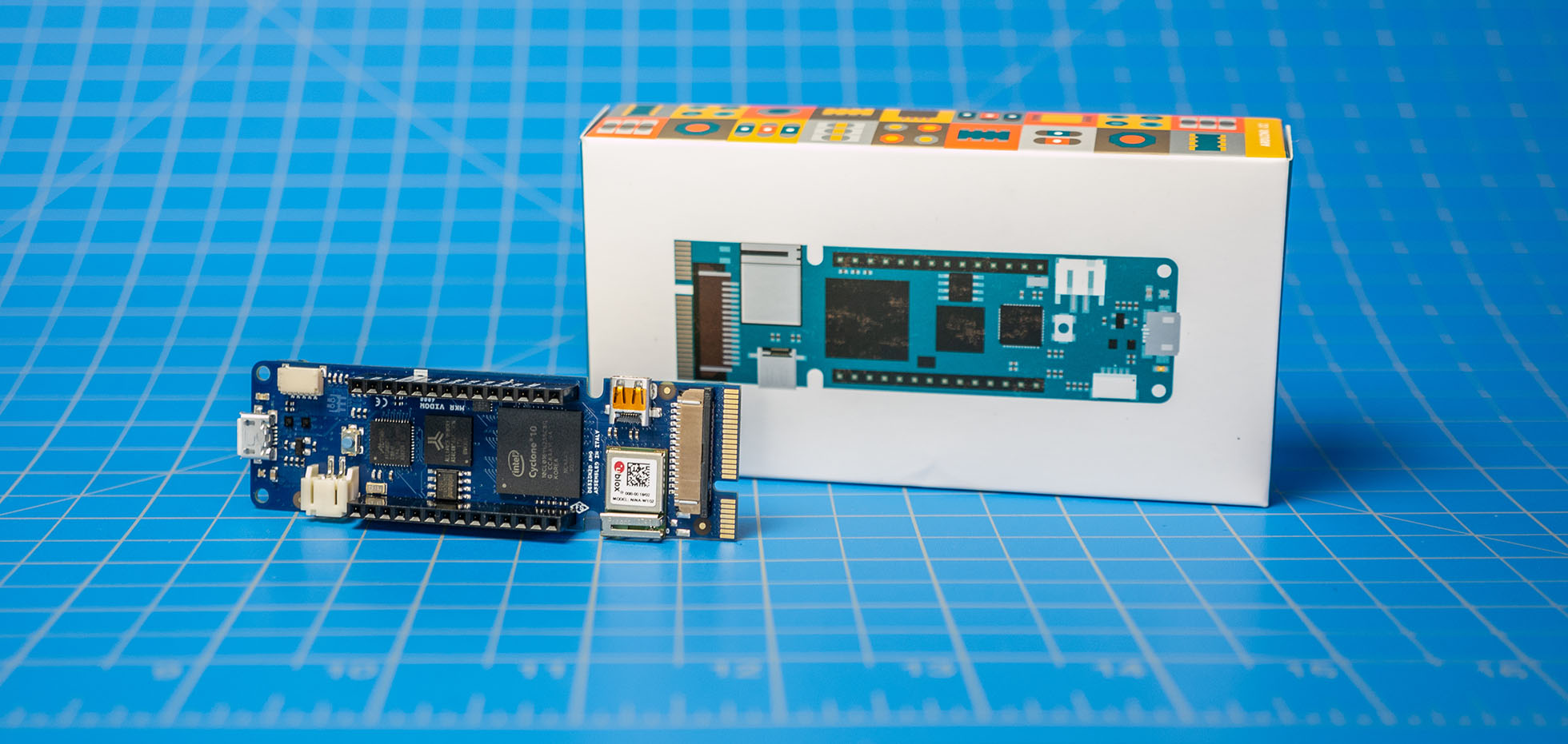
Earlier this week, I looked at the Arduino MKR Vidor 4000 during an AddOhms live stream. My goal was to understand the Vidor better. It is the new FPGA-based Arduino which started shipping this month. It runs about $60. You can learn more at the Vidor Product Page on the Arduino website.

In this post, I briefly touch on the difference between an FPGA and a microcontroller. Then I walk you around the MKR Vidor 4000’s board. Using one of the examples, I talk a bit about how the various chips communicate with each other. This section also highlights what makes the Arduino FPGA board different from other development boards. Lastly, I answer “should you buy an Arduino MKR Vidor 4000?”

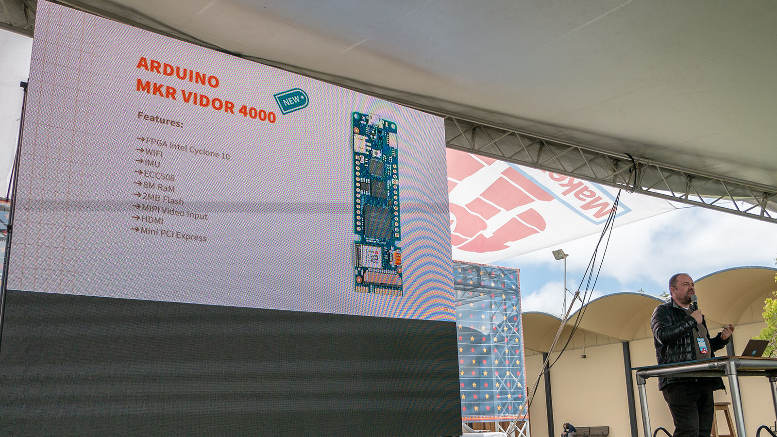
Arduino announced several new products at the 2018 Bay Area Maker Faire. One of those products is the MKR Vidor 4000, an FPGA-based board. You can read their official announcement here. (Over here is a write-up on the new Uno WiFi Rev 2.) The goal of the MKR Vidor is to make FPGA accessible to makers and innovators. It represents a new shift in hardware focus for the Arduino team.

An FPGA is a Field Programmable Gate Array. In other words, it is reconfigurable hardware. Unlike a microcontroller, an FPGA is not running software. Instead, its gate array changes configurations for a specific task.

The example I like to think about is a rotary encoder. You might find one on the spindle of a motor. As the motor spins, an IR sensor detects slits in the encoder to track speed and direction. In a microcontroller based system, you might use an interrupt to monitor the IR sensor. Even though interrupts can respond quickly, there is still a chance of missing a pulse. Plus, the rest of the microcontroller has to wait while the interrupt is handled. In an FPGA, however, you would build a hardware counter with the pulse driving the counter’s clock input. This counting happens independently of whatever else the FPGA is doing.

Previously,  I wrote a FleaFPGA Introduction. This board was about the size of an Arduino Uno with some GPIO pins, a VGA, USB, SD Card, PS2 Style Port, and a USB Host connector. At the time, the Lattice Mach XO2 provided the base logic. It found some success in the emulation community (*cough* x86 *cough*.) Unlike software emulators, the FPGA emulates the actual digital logic of classic computer ICs. Also known as ASICs.

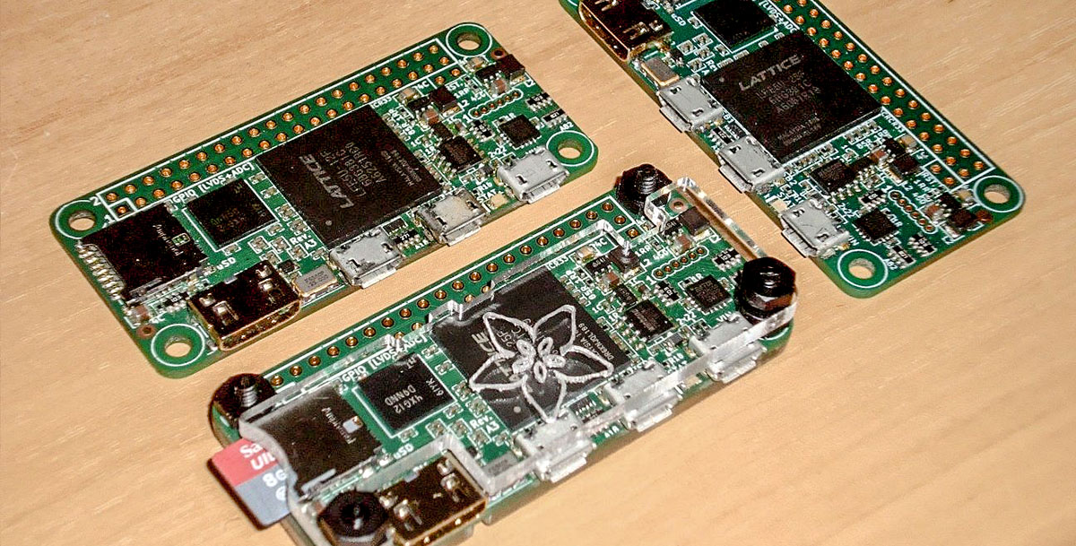
Fast forward to today, well, this week. Valentin Angelovski is at it again, but this time, with a new and improved board the size of a Raspberry Pi Zero. He’s launched an Indiegogo Campaign for the FleaFPGA Ohm. For $45 (plus a bit for shipping) you can reserve your spot for when these start shipping early next year.

As you might have noticed, I don’t often promote or comment on crowdfunded projects. My experience with crowdfunded projects has not been positive. So what makes the FleaFPGA Ohm different? Well first, I know Valentin well. Granted distance has kept us from meeting face-to-face, we talk at least once a week on IRC. I’ve been eagerly watching his progress with the FleaFPGA Ohm. Second, this isn’t his first hardware project. He’s already sold many of the original FleaFPGA boards. While there is always a risk with crowdfunded campaigns, I think the risk here is minimal–and worthwhile.

If you’re interested in advancing your hardware hacking game, FPGAs are the next step. And I think the FleaFPGA Ohm is a serious option to consider. Since you might be new to FPGAs or Valetin’s projects, I sat down to interview him for this project. (Okay, it was Google Docs, but these questions and answers are real!)

Before continuing, in disclosure, I have backed this project. However, no other endorsement or paid promotion has happened. Below here are actual answers from Valentin to questions I asked (and had.)

Back FleaFPGA Ohm on Indiegogo


Random numbers are a relative concept. In general, random numbers used in digital electronics are called Psuedo-Random sequences. There is a defined algorithm that is used to generate the sequence and does not actually occur in nature. In applications like Flashing a LED, this method is fine. However, for any level of encryption this is unacceptable.

Steve Buch at Electronics Weekly writes about how researchers Dr. Marie O’Neill and Dr. Jiang Wu at the University’s Institute of Electronics and Communications Information Technology (ECIT) has developed methods to generate true random bits digitally.

Fundamental to all of the ECIT generators is the effect of random noise during the transition from a metastable state to a bistable state.

Whether the output becomes a 0 or 1 depends on conditions, including internal noise, at the instant of input transition.

If you are giving thoughts to creating a cryptographic device, you might want to give their methods a look.