189 Results

Arduino

Search

Continuing the DIY Arduino tutorial series, this AddOhms episode shows how to create a PCB in KiCad. I make a joke that the original design was a rectangle, which I found boring and pointless. So instead, I designed a triangle to give the board 3 points. Get it? Puns! I am calling it the Pryamiduino. To be honest, I found not having a constraint to be a problem. By forcing a specific board size and shape, many decisions were more manageable.

boring rectangular arduino nano clone
First design – Boring!

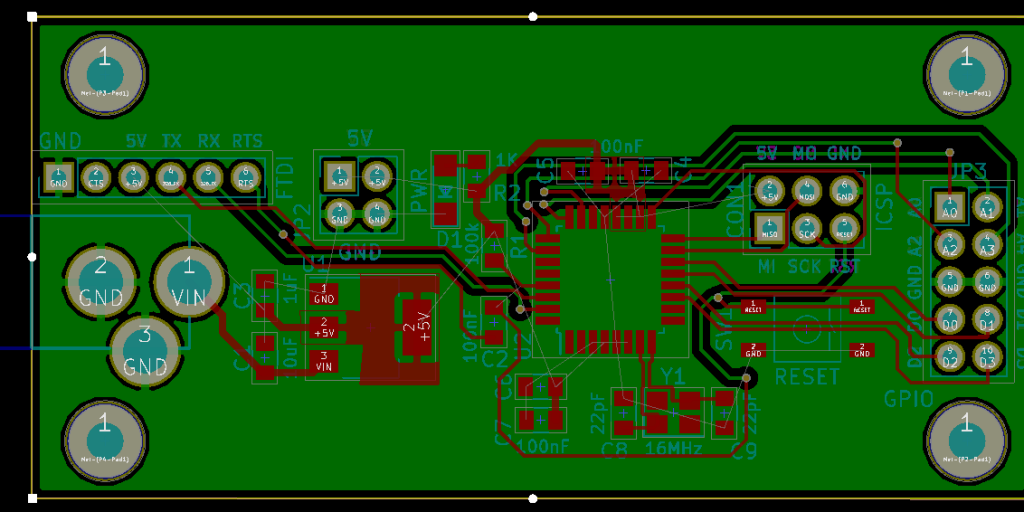
In the end, the video ended up more edited than I planned. KiCad is just so finicky and crashy that I could not make a coherent start to finish tutorial. At least, I could not work with a board at this level of complexity. Something simple like a 555 flasher would be easier to show from start to finish. I am planning some immediate follow-ups with quick tips on using KiCad. It is a frustrating suite of applications, but the results can be quite nice.

AddOhms Pyramiduino Show Notes

One of the last significant steps in a project is designing the custom PCB. This stage means creating a DIY Arduino board that is custom to the application. Two examples of my past projects are BinBoo, a Binary Clock, and Open Vapors, my reflow oven controller.

While working on a project for a friend, I got to thinking; it would be nice to have a checklist for circuit elements to include on a DIY Arduino board. In the early days, I forgot to add a filter cap to AREF, for example.

These tips are based on an 8-bit AVR design, like the ATmega328p chip. You could apply these tips to other 8-bit AVRs. Until now, I have not designed a custom board around a 32-Bit/ARM board. Though at only $16, I would be tempted to just solder the Teensy module directly to my finished board.

Below is a written list of items for a DIY Arduino checklist. If you’d like to see me design this board in KiCad, check out this AddOhms Tutorial.

When I started working on Open Vapors, I thought the stumbling point would be the PID algorithm or safe AC line control. However, it turned out; I spent a significant amount of time understanding how to print to the Arduino LCD display correctly.

Grove Character LCD with RGB Backlight

If you need an easy to use RGB LCD, check out the Grove LCD from SeeedStudio. They sent me one to check out. The LCD comes with Seeed’s “grove connector system” which can connect to a variety of their Arduino-compatible boards. You can also pick up the Grove Base Shield which adds a variety of Grove connectors to an Arduino Uno. The Grove LCD makes it super easy to connect up a character LCD. It is very plug-and-play.

As I dig into my latest project, the lessons I learned back then are coming back to me. Here are 7 tips for driving an Arduino LCD display, like one with 2×20 or 4×20 characters.

As a kid, I got the book “Upgrading and Repairing PCs.” (Now in its 22nd edition.) It was the first book to explain to me the PC architecture. I considered, how were there so few pins on an AT-style keyboard connector when there were 101 keys on the keyboard? That is when I first learned about the keyboard matrix.

Intel_P8049_AH_controller
Original image from Deskthority Wiki. (Edited image is shown.)

The keyboard matrix itself did not amaze me, but instead the idea there was an entirely separate 8-bit microcontroller inside of the keyboard. Early keyboards may have used the P8049AH, which, there is still some stock available to purchase. I was fascinated with the idea an entire computer was necessary to run the keyboard, to use my “real” computer. Why did it take something as complicated as a microcontroller?

A question came up on IRC regarding how to PWM a 3-pin PC fan with an Arduino using analogWrite(). Controlling the fan was seemingly straightforward. The problem was that the hall effect sensor, or TACH signal, was incredibly noisy. The noise made it impossible to measure the fan’s rotation. Working through the question, I found three issues to tackle:

  1. You need to use a PNP transistor
  2. Filter capacitors help
  3. Create a non-blocking RPM measurement (with millis())

This post addresses all three issues regarding how to PWM a 3-pin PC fan with an Arduino.