Category

Tutorials

Category

r-2r matrix illustration

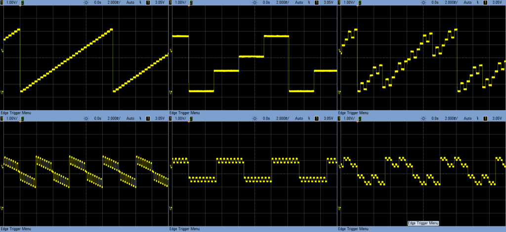
Creating real analog outputs from a digital pin is possible when you use an R-2R DAC. What is a DAC? The letters stand for Digital to Analog Converter. This simple DAC is built using resistor. The principle works on voltage dividers. By enabling different combinations of resistors, it is possible to get various voltage levels.

Obviously, such a simple design will have some trade-offs.

The resolution depends on how many resistor steps you include. That is why discrete R-2R networks built on a breadboard have a staggered look. You could add more levels to smooth it out, or there are other options.

This R-2R Logic Noise Post talks about how they work in detail and even includes a section on filtering the output to be less “stepped.”

Can’t find the digital chip you need on Mouser or just wish you could make it yourself? With the FleaFPGA board, you can! As a college freshman, we heard rumors of a custom Integrated Circuit (IC) class. Surely what had to be a senior level class, I couldn’t wait until I understood electrical engineering enough that I got to make my own IC!

Two years passed, I was learning Verilog and VHDL in a class titled “Complex Programmable Logic Devices.” In short, CPLD. Those devices were the precursors to today’s modern FPGA devices.

In short, FPGAs, allow you to create your own IC with “software.” The best part? You can quickly reprogram that to fix bugs, add features, or operate completely differently just as fast as you can flash a new sketch into an Arduino Uno.

Introducing the FleaFPGA, a fully functional FPGA board perfect for beginners or veteran chip designers ready to create “chips” on their own.

Last week I had a detailed Arduino tutorial on software pulse width modulation using millis() and micros(). Why? Because I wanted to create a Proper Larson Scanner, with persistence and at least 8 LEDs.

From Amazon

Even though it is a popular project for the Arduino Uno, most Larson scanner tutorials, like my first one, have a few flaws. First, there is no persistence, or tail, to the LED as it moves back and forth. Persistence could be solved by using pulse-width-modulation. The Uno and other 328p-based micros only have 6 Pulse Width Modulation (PWM) pins. And let’s be honest, every project is made better by adding more LEDs. 🙂

If you look at this cover shot of KITT from Knight Rider you will see there isn’t just a single light source. It appears multiple lights are turned on, as well as fading effect. This fading effect creates a tail. Of course, the reason is probably that standard light bulbs were being used back in the 80s. Traditional light bulbs don’t turn on or off nearly as fast as LEDs.

Presenting the Proper Larson Scanner

Knowing that a popular Halloween hack is to add Cylon (or KITT) lights to your pumpkins, I thought it was time for a Proper Larson Scanner. This code example does a couple of important things.

  1. It implements my “software pulse width modulation.”
  2. Can be used on all 20 I/O pins of an Uno (or other 328p Arduino)
  3. Does not use any delay()s!

So if you want to make your pumpkin even more Cylon-like this Halloween, check out this full tutorial on a proper Larson scanner.

While I was attending a material science conference, I learned the value of listening to something new. The paper I came to see was finished, and the next was about to start. It was titled, “Additive Manufacturing.”

I almost left!

What a dull phrase, right? Well, I was stuck in the middle of a row with four people on either side of me. So I decided, it was a good time to catch up on Reddit. What I didn’t realize is “additive manufacturing” is what almost everyone else in the world calls “3D Printing.” Plus, this presenter was talking about doing it with metal!

When you think about it, most extrusion-based 3D printers are laying down material one layer at a time. In other words, they are manufacturing an object by “adding” material. See the connection? Most people probably lump 3D-printing into rapid prototyping and additive manufacturing into a “real” production process.

One more story.

At SXSW one year, I attended an event held by Shapeways. Objects they made were all over the venue, and they looked incredible. Plus, some were for sale. My favorite? Super Mario Bros related stuff. Do a search for “Mario” in Shapeways marketplace for some neat things to add to your desk.


The Arduino Uno has six pins dedicated to Pulse Width Modulation (PWM). PWM is great for analog-like control for the speed of motors or LED fading. But what if you want to control more than 6 devices? Or what if you’re using the PWM pins to control servo motors, but still want to fade an LED on a 7th pin?

One option is to change boards and processors. For example, you could move up to the Arduino Mega 2560. That means a bigger board and more cost.

Using millis() and micros(), it is possible to do PWM entirely in software. The best part is; if you can set the pin to OUTPUT, you can use this technique.

This tutorial will explain how you can use micros() and millis() to get more PWM pins on an Arduino Uno, Nano, or Pro Mini. It will probably work on other boards and processor types, but I haven’t tested them yet.

There’s a reason I needed this software PWM code. Subscribe to the mailing list, RSS feed, or follow me on social media to see why next week…

Apologies to the email subscribers if the code isn’t formatted correctly. Click here to read the full post.